A GGD switchgear enquiry should describe the electrical installation, not just the cabinet you expect to receive. A voltage, an incoming current and a quantity of panels leave too much room for different interpretations of the same project.
The better starting point is a coordinated request for quotation, or RFQ. This guide explains what to send, which ratings to keep separate and how to turn an initial proposal into an equipment specification that both the buyer and manufacturer can approve.
Table of Contents
What Are You Buying When You Specify GGD Switchgear?
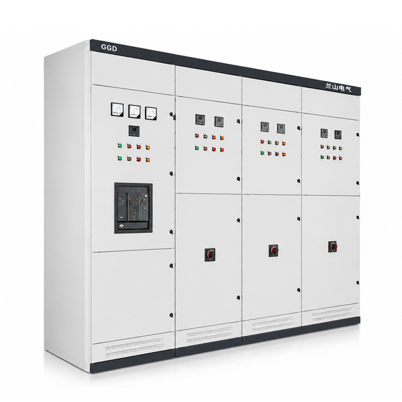
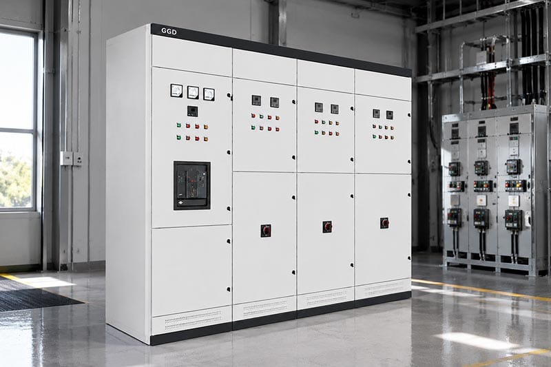
Lanshan’s GGD low voltage switchgear is an indoor, fixed-structure assembly for power distribution, control and electrical protection. Its published arrangement includes incoming, distribution, metering and cable-connection sections.
The product name is the starting point, not the complete specification. Identify the actual incoming device, outgoing circuits, internal layout and installation requirements. Do not assume that a fixed cabinet provides the same functional-unit replacement arrangement as a drawer-based system.
For an IEC-based project, IEC TR 61439-0 explains the application characteristics that specifiers and manufacturers need to agree. Use that framework to turn a product preference into a defined assembly requirement.
For background on the system’s role, see Lanshan’s guide to low voltage switchgear in industrial projects.
The Essential GGD Switchgear RFQ Document Pack
Organize the enquiry around five documents. They can be preliminary during the first discussion, provided assumptions and missing information are clearly identified.
| Document | What to include | What the supplier should return |
|---|---|---|
| Single-line diagram | Sources, incomers, bus sections and outgoing circuits | Proposed circuit arrangement and deviations |
| Load and feeder schedule | Design currents, operating duties and circuit functions | Device selections and supported loading conditions |
| Technical requirements | Supply characteristics, fault data, environment and applicable standards | Configuration-specific rated-data schedule |
| Installation drawing | Room limits, cable routes, entries and access | General arrangement and connection details |
| Acceptance schedule | Required evidence, inspections and approval stages | Verification documents and proposed test plan |
Give each GGD switchgear document a revision and status. A load schedule marked “preliminary” should not silently become the manufacturing basis because it was the only attachment available.
Use consistent cabinet and feeder identifiers across the package. If feeder F03 is a pump supply in the load schedule, the single-line diagram, component list and terminal drawing should all refer to that same circuit. This gives later clarifications a precise reference instead of relying on descriptions such as “the third breaker.”
Show Supply Modes on the Single-Line Diagram
For GGD switchgear, identify whether the assembly receives one transformer supply, an alternative generator supply or multiple permitted sources. Mark the normal positions of incomers and any bus coupler.
Show which source combinations are prohibited. If transfer is required, define whether it is manual or automatic, the permitted interruption and the controls included in the order. Do not let two incoming devices imply a transfer scheme that nobody has specified.
Include the upstream protective-device information and the point at which the available fault data apply. Have the project engineer identify the relevant source configurations for the short-circuit study.
Keep this drawing focused on operational intent. A supplier can propose equipment against an agreed operating arrangement; it should not have to invent the site’s supply philosophy from a panel quantity.
Give Every Feeder a Load, Not Just a Breaker Size
The feeder schedule should include design current and whether loading is continuous, intermittent or shared with other circuits. BEAMA’s assembly-specification guidance highlights these inputs because circuit position and adjacent loading affect the proposed assembly.
For GGD switchgear serving production equipment, describe normal operation, startup and any approved expansion separately. Label spare ways as installed spare devices, unequipped spaces or future extensions; those are different deliverables.
Keep Electrical Input Separate from Motor Output
A motor’s shaft-output rating is not its electrical input. For a balanced three-phase load with known electrical input, the Department of Energy’s three-phase power relationship can be rearranged as:
Current (A) = electrical input (kW) × 1,000 ÷ (√3 × line voltage × power factor)
For illustration, 30 kW electrical input at 415 V and 0.88 power factor gives approximately 47.4 A. This is a running-current calculation, not an automatic breaker or cable selection. Starting duty, protection and installation conditions still require engineering review.
Separate Assembly Ratings from Breaker Ratings
A GGD switchgear submission should distinguish the complete assembly from the devices inside it. IEC 60947-2 covers circuit breakers, while IEC 61439 addresses assembly characteristics and verification.
Use the following distinctions when reviewing a rated-data schedule. Breaker breaking capacities and assembly withstand ratings describe different duties and cannot be substituted for one another.
| Rating or requirement | What the proposal needs to state |
|---|---|
| Assembly and circuit current ratings | Current capability under the agreed loading and environmental conditions |
| Short-time withstand current, Icw | Withstand current together with its specified duration |
| Peak withstand current, Ipk | The applicable peak-current capability |
| Conditional short-circuit current, Icc | The rating and the specified short-circuit protective device on which it depends |
| Breaker Icu and Ics | Ultimate and service short-circuit breaking capacities at the relevant voltage |
For GGD switchgear, “50 kA” alone is an incomplete answer. Ask which characteristic it describes. Do not infer a one-second or three-second duration when none is declared.
Where a conditional rating is offered, record the exact protective-device selection and the conditions supporting it. Treat a later substitution as a review item. The purchase specification should preserve the verified arrangement, not just retain the same headline fault-current number.
Likewise, an incoming breaker’s frame size should not be accepted as the assembly’s guaranteed continuous-current capability.
Define What Each Outgoing Circuit Actually Includes
A circuit labeled “pump” might supply a separate starter, contain a starter within the panel, or feed a drive supplied elsewhere. Resolve that boundary before approving the GGD switchgear component schedule.
For each motor circuit, state who supplies the starting equipment, overload protection, control supply and process-interface wiring. Identify whether the order includes only distribution protection or the complete agreed motor-control function.
Agree Protection Coordination Responsibilities
Ask who performs the protection study, approves the settings and checks coordination with adjacent equipment. IEC TR 61912-2 provides guidance on selectivity between low-voltage overcurrent protective devices; different breaker sizes alone do not demonstrate it.
For GGD switchgear with adjustable protection, include the approved settings in the handover documents. Device substitutions should receive a technical review rather than being treated as equivalent because their nominal current matches.
State the Neutral and Protective-Earth Arrangement
Send the site’s earthing arrangement with the GGD switchgear enquiry. Ask the engineer to define the neutral and protective-earth connections, conductor requirements and any required neutral switching.
A phrase such as “three-phase, four-wire” should not replace a connection drawing. Mark where external conductors terminate and identify the responsibilities on both sides of the interface.
Where electronic loads or significant phase imbalance are expected, provide the relevant load information and request a specific neutral assessment. Do not assume that a standard neutral arrangement is suitable for every circuit mix.
Approve Cable Space Before Fixing Cabinet Dimensions
For every GGD switchgear connection, provide cable material, conductor cross-section, quantity per phase and entry direction. BEAMA’s guidance also recommends specifying the actual external connections, including busbar trunking where used, rather than relying on default termination assumptions.
Then request a dimensioned interface drawing showing the gland plate, terminal locations, working space and connection clearances. Include cable support and access to the terminals.
For example, a proposal may have enough terminals for the number of feeders but insufficient room for the selected parallel cables. That is an interface problem a panel-front drawing will not reveal.
Mark walls, trench edges, columns and door swings on the installation plan. Have the supplier confirm the offered access arrangement before a cabinet width or depth becomes a fixed civil constraint.
Assign responsibility for cable lugs, gland plates, site drilling and bus connections. An accessory excluded from the cabinet supply still needs an identified supplier and an approved interface; it should not become an improvised installation decision.
Specify Environment and Temperature-Rise Conditions Together
Lanshan lists GGD switchgear for indoor installation. Do not turn an indoor configuration into an outdoor product merely by selecting a protection degree from a series table.
State room temperature, altitude, humidity, contamination and any unusual exposure. IEC 60529 classifies enclosure ingress protection; an IP designation is not a complete environmental specification.
The IEC 61439-1 framework includes group rated current and temperature-rise verification. Ask the manufacturer to confirm the loading supported by the offered component arrangement, enclosure and cooling provisions.
For GGD switchgear, review changes to ventilation openings, filters or fans together with the thermal assessment. Avoid approving an enclosure revision while leaving the previous loading assumptions unquestioned.
Check Maintenance Access for the Fixed Arrangement
Ask the supplier to mark the isolation boundary for replacing an outgoing device and accessing its cable terminals. Separately identify the boundary for work on the main bus.
For GGD switchgear, the required form of internal separation must be agreed and shown on the drawings. IEC 61439-2 addresses power switchgear and controlgear assemblies, including internal-separation requirements.
Describe the task the plant needs to perform instead of requesting only “easy maintenance.” Maintenance must follow the manufacturer’s instructions and approved site isolation procedures, with appropriately qualified personnel.
Replace “Remote Monitoring” with a Signal Schedule
For GGD switchgear, list the required measurements and indications: incoming current, energy consumption, breaker position or trip status, as applicable. Separate monitoring from permission to issue switching commands.
Identify the control voltage, communications interface, external system and responsible integration party. Ask what happens to each required function when auxiliary power or communications are unavailable.
Agree the acceptance test for every supplied interface. If the supplier demonstrates an output at a terminal block, identify who will verify that the intended signal reaches the site’s control system.
A defined signal schedule makes proposals comparable. An undefined promise of a “smart cabinet” does not tell either party what must be delivered.
Request Verification Evidence Before Manufacturing Approval
Specify the applicable assembly standard, edition and local project requirements. For GGD switchgear assessed under IEC 61439, Part 1 contains general rules and is used with the relevant product part; a reference to Part 1 alone is not the complete conformity basis.
Keep design verification and routine verification distinct. The former addresses the design’s compliance; the latter checks the manufactured assembly. BEAMA’s verification guide explains those separate responsibilities.
Request an evidence schedule linking the offered configuration to the relevant documents. Where the arrangement differs from a verified design, ask for the technical basis supporting that difference.
Agree the factory acceptance scope separately. Functional demonstrations, labels and drawing checks do not replace evidence of thermal or short-circuit capability.
Write the Functional Acceptance Tests Early
For GGD switchgear with controls, describe the expected result of each agreed test: a position indication changes correctly, an external trip command operates the assigned device, or a prohibited closing command is blocked. Identify simulated inputs and equipment excluded from the demonstration.
Record the drawing revision and device settings used during the test. Assign responsibility for the site connections and end-to-end checks that cannot be completed in the factory. This keeps factory acceptance focused on the supplied assembly without pretending it proves the entire installed system.
Example: Two Offers That Look Identical Until Installation
Consider a hypothetical enquiry for 400 V GGD switchgear with a requested 1,000 A assembly rating and six outgoing circuits. These are illustrative requirements, not a confirmed Lanshan configuration.
The buyer initially sends only those figures and a panel quantity. One supplier assumes the pump circuits feed separate starters. Another includes motor-control components. Both assume a cable arrangement that has not been approved.
The revised enquiry identifies two pump circuits with external starters, three distribution feeders and one fully equipped spare. It supplies the simultaneous load scenario, actual cable schedule and required control signals.
The room plan then shows that the proposed rear-access space is unavailable. The layout needs revision or a different verified access arrangement before either offer can be accepted.
This GGD switchgear comparison is now useful because it exposes differences in deliverables, not just names and headline ratings. The missing information was the circuit and installation definition, not another generic product brochure.
Close Technical Deviations Before Releasing the Order
For each GGD switchgear offer, maintain one clarification register. Give every unresolved point an owner, required document and approval status.
Before manufacture, agree the single-line diagram, rated-data schedule, component list, general arrangement, connection drawings and test plan. Mark which documents are informational and which require approval.
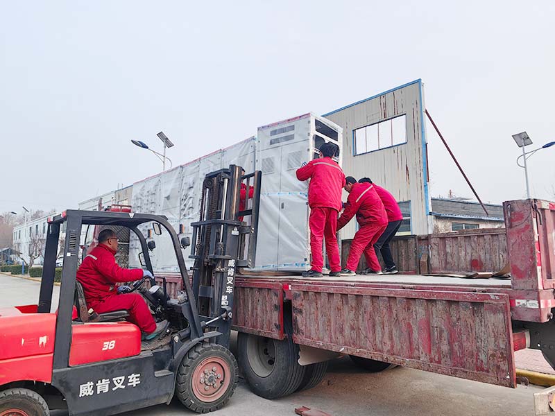
Also define shipping sections, reassembly responsibilities and the final documentation package. A change to feeder quantity, cable size or protective device should update the affected drawings and verification review, not remain buried in an email.
Review Lanshan’s low voltage distribution equipment against that coordinated package. Request configuration-specific guarantees rather than treating the largest number in a product-family table as the rating of every cabinet.
Conclusion
A complete GGD switchgear RFQ connects the supply arrangement, feeder duties and site interfaces to an agreed assembly specification. Keep current ratings distinct, make installation constraints visible and resolve verification requirements before manufacturing approval.
Contact Lanshan Electric with your single-line diagram, feeder schedule and installation drawings to discuss a GGD configuration matched to your project.
FAQ
What is GGD switchgear used for?
Lanshan’s GGD series provides indoor low-voltage distribution, control and protection in a fixed cabinet arrangement. The exact incomer, outgoing circuits and monitoring functions are selected for the project.
What should I send for a GGD switchgear enquiry?
Provide a single-line diagram, feeder schedule, supply and fault data, installation drawing and acceptance requirements. Mark preliminary information clearly and identify what must be confirmed before manufacturing approval.
Is a GGD cabinet the same as withdrawable switchgear?
No. The published GGD arrangement is fixed. Confirm the actual device mounting, isolation boundaries and replacement access rather than assuming the maintenance arrangement of a drawer-based assembly.
Does a 50 kA breaker establish the cabinet’s fault rating?
No. A breaker’s breaking capacity and the assembly’s short-circuit capability are different characteristics. Review the complete assembly rating, associated conditions and any specified protective device on which the rating depends.
Can I request GGD switchgear before the design is finished?
Yes. Submit the available drawings and a list of unresolved inputs. Request a conditional proposal that identifies assumptions and approval points, then update the specification before releasing equipment for manufacture.