An EV charging substation should be designed from the charging duty that the site must deliver, not from the sum of charger nameplate ratings alone. A site with twenty chargers can impose very different transformer demand depending on charger power, vehicle dwell time, charging schedules, load management and future expansion.
For project owners and EPC teams, the goal is to convert those operating assumptions into electrical requirements that a supplier can actually build and verify. This guide explains the specifications that should be defined before requesting an EV charging substation, including transformer duty, medium-voltage connection, low-voltage distribution, protection, power quality, monitoring and the next expansion stage.
Start with the Charging Service the Site Must Deliver
The first specification for an EV charging substation is not transformer kVA. It is the charging service objective. Record the number of charging ports, rated power of each charger, expected vehicle types, typical dwell time, arrival pattern and the energy that vehicles need before departure.
The NREL EVI-LOCATE planning tool starts site analysis with charger requirements and existing electrical infrastructure, including transformers and service panels. That is the right planning order: define the charging requirement, then evaluate what electrical capacity is needed to support it.
For fleet depots, include the departure schedule. Ten vehicles that remain parked overnight create more scheduling flexibility than ten vehicles that arrive together and need a rapid turnaround. For public fast-charging sites, coincidence can be higher and less predictable. A project specification should describe these operating cases instead of applying one generic demand factor to every site.
Do Not Size the Transformer from Charger Nameplates Alone
Adding every charger rating gives the maximum installed EVSE capacity, but it does not automatically equal the maximum demand seen by the EV charging substation. The transformer must be sized against a justified operating profile, including any non-charging loads supplied by the same station.
Build Three Demand Cases
At minimum, prepare a normal operating case, a credible high-demand case and the planned future case. Keep them separate. The normal case reflects typical scheduling; the high-demand case tests the site during a busy period; the future case includes approved charger additions or fleet growth.
If the EV charging substation also supplies lighting, payment equipment, cooling systems or site auxiliaries, include those loads in the same time-based schedule. Do not add them after the transformer has already been selected.
| Planning input | What to define | Why it changes the substation |
|---|---|---|
| Charging ports | Quantity and rated power per port | Sets installed charging capacity |
| Coincidence | How many ports may charge at high power together | Drives maximum site demand |
| Energy requirement | kWh needed before vehicle departure | Determines whether power can be shifted in time |
| Existing site load | Peak demand already using the service | Reduces capacity available for charging |
| Future expansion | Approved additional ports and power | Affects transformer, bus and space reservations |
| Load management | Power ceiling and control behavior | Can reduce coincidence when operationally acceptable |
Use Managed Charging as a Defined Design Input
Load management can reduce the peak seen by an EV charging substation, but only when the operating strategy is specified and dependable. It should not appear in the calculation as an unexplained diversity percentage.
For procurement, state the maximum site power ceiling, the minimum charging service that must still be delivered and what happens if the load-management controller or communications link is unavailable. If loss of control causes all chargers to revert to maximum demand, the transformer and low-voltage system need to be assessed for that condition or another fail-safe behavior must be defined.
Do Not Confuse Load Management with Spare Capacity
A managed EV charging substation can operate below the arithmetic sum of charger ratings, but this does not create unlimited expansion capacity. When more chargers are added, the available energy during the charging window may become the limiting factor even if the instantaneous power ceiling remains unchanged.
Define the Transformer Duty from kW, kVA and Power Factor
The transformer in an EV charging substation supplies apparent power, so the project should provide expected real power and power factor at the relevant operating points. For a balanced three-phase planning case, apparent power can be estimated as:
Transformer demand in kVA = site demand in kW ÷ power factor
Assume, for illustration, that managed charging limits the charging load to 1,200 kW while auxiliary loads add 60 kW. If the aggregate input power factor at that operating point is 0.98, the apparent demand is approximately 1,286 kVA. This is a planning example, not a Lanshan product rating or a recommended loading level.
The next step is not automatically to select the nearest standard size. The EV charging substation review still needs ambient conditions, load duration, harmonics, cooling, expected growth and utility requirements. The transformer should be confirmed under the applicable IEC 60076-1 general framework and the relevant project standards.
Specify the Medium-Voltage Utility Interface Early
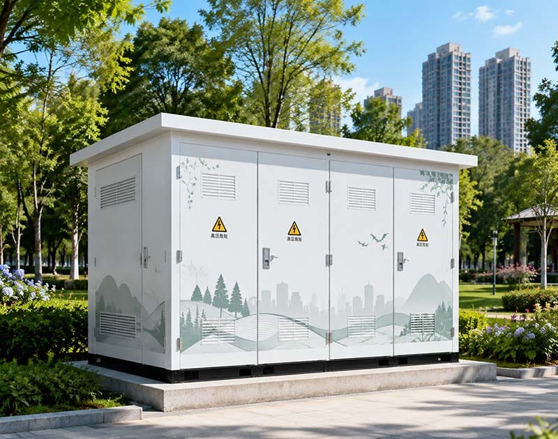
An EV charging substation often connects a medium-voltage utility supply to a lower-voltage AC bus used by the charging equipment. Provide the incoming system voltage, frequency, earthing arrangement, available fault data, metering boundary and utility protection requirements before the MV arrangement is finalized.
For a prefabricated station within its scope, IEC 62271-202:2022 addresses service conditions, rated characteristics, construction and testing for enclosed prefabricated substations above 1 kV and up to 52 kV. The EV charging substation supplier should confirm which complete assembly configuration and evidence apply to the project rather than relying only on component certificates.
Choose the Transformer and Enclosure as One Thermal System
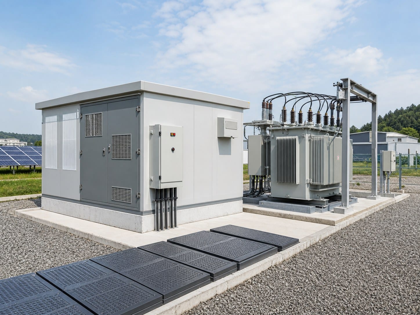
The transformer nameplate does not by itself establish the continuous capability of an enclosed EV charging substation. Transformer losses, solar heating, ventilation paths and the temperature limits of nearby switchgear and electronic controls all affect the station-level thermal design.
IEC 62271-202:2022 specifically includes temperature-rise considerations for prefabricated substations and an informative procedure for evaluating solar radiation. For an outdoor EV charging substation, provide the actual ambient range, altitude, solar exposure and enclosure location rather than simply writing ‘outdoor installation.’
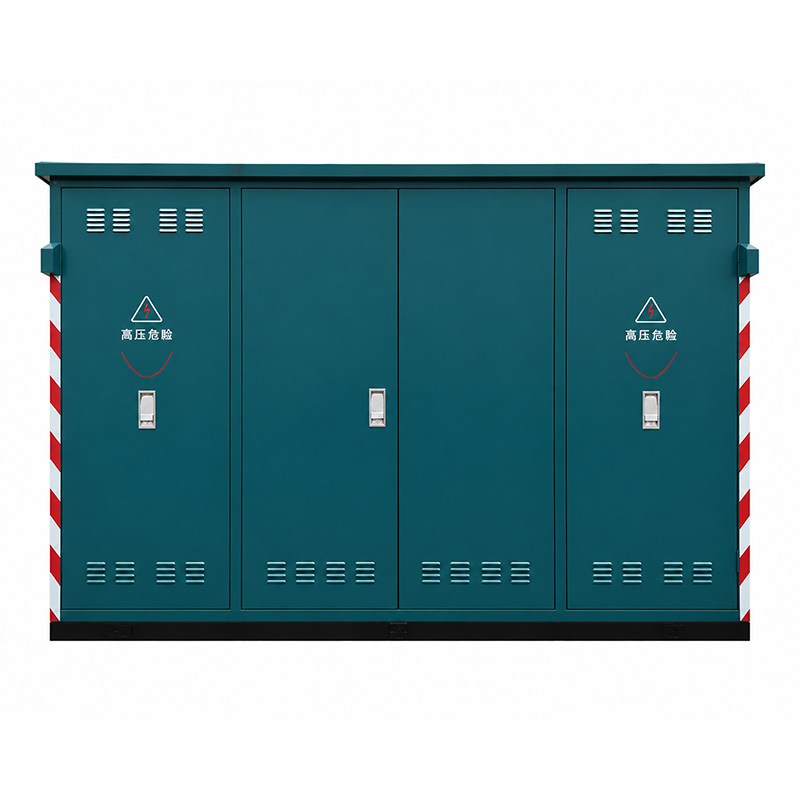
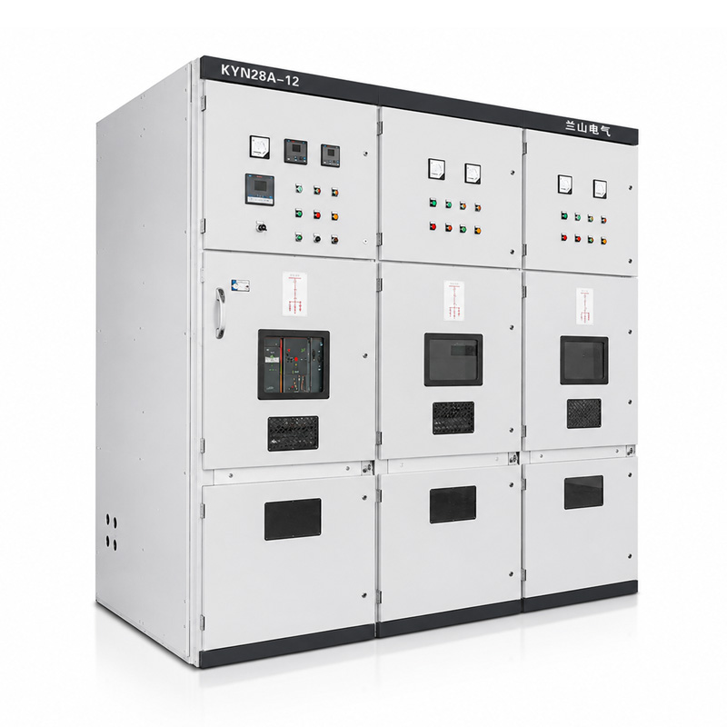
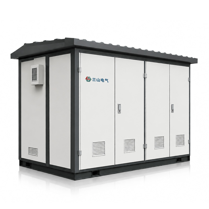
Lanshan’s EV charging station transformer solution is presented as an integrated arrangement combining medium-voltage equipment, a transformer, low-voltage distribution, monitoring and protection. The product page lists configurable transformer capacity, dry-type or oil-immersed construction and outdoor enclosure options. These are series-level options that need to be confirmed for the specific EV charging substation offered.
Plan for the Site Load Profile, Not Only the Peak
Fast-charging demand can rise and fall repeatedly. Provide the expected duration and frequency of high-load periods. A transformer carrying a short peak followed by a long recovery period is not experiencing the same thermal duty as one operating near that level continuously through the day.
Design the Low-Voltage Bus Around Charger Inputs
The low-voltage section of an EV charging substation must distribute power to the charger inputs under the selected operating modes. Provide charger input voltage, phases, rated input current or power, number of feeders and any grouping arrangement.
For an IEC-based low-voltage assembly, IEC 61439-2:2020 covers power switchgear and controlgear assemblies up to 1,000 V AC or 1,500 V DC within its scope. Request assembly-level current and short-circuit characteristics rather than treating breaker ratings as proof of the complete low-voltage panel capability.
Define spare feeders separately from future panel space. A fitted spare breaker, an empty compartment and an extensible bus section represent different levels of future readiness.
Check Feeder Diversity Against the Control Strategy
If the EV charging substation is sized around managed charging, the feeder and bus arrangement must still support the permitted charger combinations. The control strategy should not depend on a physical distribution arrangement that cannot carry a legitimate operating mode.
Keep Charger Standards Separate from Substation Standards
The EV charging substation supplies the charging equipment, but it is not itself the EV charger. IEC 61851-1:2017 addresses general requirements for EV supply equipment, while IEC 60364-7-722:2018 addresses low-voltage circuits intended to supply energy to electric vehicles and circuits for feeding energy back from vehicles within its scope.
These requirements should be coordinated with the transformer, MV switchgear and LV assembly standards rather than merged into one generic compliance statement. A certificate for a charger does not establish transformer performance; a transformer test report does not establish charger conformity.
Review Harmonics and Power Quality Before Final Sizing
EV chargers are power-electronic loads. A large concentration of converters can affect the current waveform and the wider electrical network. IEC TR 61000-2-15:2023 discusses network characteristics with high penetration of power-electronic converters, including harmonics, supraharmonics and resonance phenomena, and explicitly includes EV battery chargers among the converter sources considered.
For the EV charging substation, request charger harmonic-current information at representative loading levels and ask the electrical engineer to assess transformer capability, neutral loading where applicable, voltage distortion and any resonance risk. Do not apply a generic harmonic percentage to every charger model.
Calculate Short-Circuit Duty for Every Permitted Operating Mode
The EV charging substation short-circuit study should include the utility source, transformer impedance, cables and any permitted parallel source or on-site generation. Continuous load current and short-circuit current are separate design inputs.
On the low-voltage side, transformer impedance has a strong influence on prospective fault current. Changing the transformer design can therefore change the required switchboard capability even when the kVA rating remains the same.
Ask the protection engineer to identify the fault duties at the MV and LV buses and the interrupting devices responsible for clearing each fault. Keep assembly withstand ratings, breaker breaking capacities and internal arc classifications in separate fields in the technical schedule.
Define Protection, Metering and Emergency Functions
An EV charging substation proposal should identify the protection zones from the utility incomer through the transformer and low-voltage charger feeders. State who develops the protection settings, who approves them and who verifies them during commissioning.
Where emergency shutdown is required, define its scope. Does it disable charger output only, open LV feeders, trip the transformer supply, or initiate another approved sequence? The answer belongs in the operating philosophy and should be coordinated with local safety requirements and the charger manufacturer.
Plan Communications Without Making the Substation a Software Project
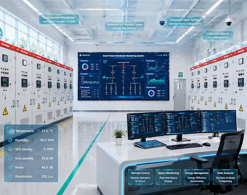
Monitoring can make an EV charging substation easier to operate, but the electrical supplier needs a precise signal list. Define transformer temperature, MV device status, LV breaker status, current, voltage, energy and alarm points that must be available.
State the required communications interface and the party responsible for integrating those points into the charger-management, site-energy or supervisory system. Do not use terms such as ‘smart monitoring’ as a substitute for a point list.
Reserve Expansion Capacity Where It Actually Matters
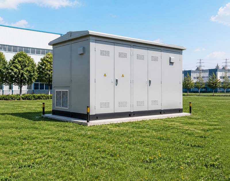
For an EV charging substation, future readiness has at least five dimensions: utility service capacity, transformer capacity, LV bus capacity, feeder space and physical site space. Reserving only one of them does not make the entire station expandable.
Suppose phase one contains eight 180 kW chargers and phase two adds four more. If phase one uses load management to cap site demand, the same transformer may or may not support phase two depending on the energy required within the charging window. Review both instantaneous power and total energy-delivery requirements.
Ask how the future feeders will be connected, whether the enclosure has a verified expansion arrangement and what outage is required for the work. Also confirm whether the utility fault level or approved service capacity is expected to change before the expansion.
Example: Turning Charger Count into an RFQ
Consider a hypothetical logistics depot planning twelve DC chargers, each with a 180 kW maximum output. The arithmetic charger total is 2,160 kW, but the fleet returns in two waves and remains parked for several hours. The operator proposes an initial EV charging substation power ceiling of 1,500 kW for charging, with 80 kW of station auxiliaries.
Assume the aggregate input power factor during the high-demand case is 0.98. The planning apparent demand is approximately 1,612 kVA. That number is only the start of the transformer review; it does not select a standard rating by itself.
The RFQ should state the 1,500 kW charging ceiling, 80 kW auxiliary demand, charger input characteristics, expected duration of the high-load period and the control behavior if the management system fails. It should also define the phase-two charger count.
The supplier can then review a transformer and station arrangement against one documented operating model. Without those inputs, one offer may assume all chargers run simultaneously while another assumes aggressive diversity, making the quotations technically incomparable.
Use a Complete EV Charging Substation RFQ Checklist
| RFQ section | Information to send | Supplier response to request |
|---|---|---|
| Charging duty | Port count, charger input ratings, dwell and energy requirements | Supported site demand and assumptions |
| Load management | Power ceiling, control logic and failure mode | Maximum demand used for equipment selection |
| Utility interface | MV voltage, fault level, metering and ownership boundary | MV switchgear and protection arrangement |
| Transformer | kW/kVA profile, PF, harmonics, ambient and growth | Capacity, impedance, cooling and guaranteed data |
| LV distribution | Feeder schedule, charger inputs and spare circuits | Bus ratings, breaker schedule and short-circuit capability |
| Monitoring | Point list, communications protocol and integration owner | Available signals and interface responsibility |
| Site conditions | Layout, altitude, temperature, solar exposure and access | Enclosure, thermal and installation limitations |
| Expansion | Future charger count and target date | Reserved capacity, physical provision and required outage |
Send the same package to every bidder. A comparable EV charging substation proposal should identify assumptions and technical deviations rather than filling missing data with silent defaults.
What to Confirm in a Lanshan Configuration
Lanshan’s EV charging station transformer is positioned as an integrated supply solution for charging infrastructure with MV equipment, transformer, LV distribution and monitoring/protection functions. Its published technical range includes project-specific grid voltage, 50/60 Hz operation, outdoor installation, dry-type or oil-immersed transformer options and configurable station capacity.
Treat those published ranges as configuration starting points. Request a project-specific rated-data sheet, single-line diagram, enclosure drawing and verification schedule. Confirm which options apply to the offered unit and which site or utility requirements remain outside the equipment supply.
For a coordinated review, send Lanshan the charger schedule, utility connection data, site layout, existing demand and future expansion plan. That information allows the EV charging substation discussion to focus on the actual charging service rather than an assumed charger coincidence factor.
Conclusion
A well-specified EV charging substation connects the charging service objective to transformer capacity, utility constraints, low-voltage distribution and the site expansion plan. The most important number is not the sum of charger nameplates; it is the justified demand the station must support under defined operating conditions.
Define load management, protection, harmonics, thermal conditions and monitoring before approving equipment. Contact Lanshan Electric with your charger schedule, utility data and site layout to discuss an EV charging power-distribution configuration for your project.
FAQ
How do I size an EV charging substation?
Start with charger input power, expected coincidence, vehicle dwell time, existing site demand and any managed-charging limit. Convert the justified maximum demand to kVA using the corresponding power factor, then review harmonics, thermal conditions, fault duty and growth before selecting the transformer and station configuration.
Should transformer capacity equal the sum of all charger ratings?
Not necessarily. Managed charging and diversity can reduce simultaneous demand, but the assumptions must be supported by the required charging service and failure behavior. For a public high-power site with limited scheduling flexibility, coincidence may be materially higher than at an overnight fleet depot.
What standards apply to an EV charging substation?
The applicable set depends on the equipment and location. IEC 62271-202 can apply to prefabricated MV/LV substations within its scope; IEC 60076 covers power transformers; IEC 61439-2 covers relevant LV assemblies; IEC 61851 and IEC 60364-7-722 address EV supply equipment and EV supply circuits within their scopes. Local utility and installation requirements also need confirmation.
Can load management let me use a smaller transformer?
It can reduce the maximum demand used for design when the operating strategy is credible and enforceable. Define the power ceiling, minimum charging service and fallback behavior, then verify that the selected transformer and distribution system support every permitted operating condition.
What information should I send for an EV charging substation enquiry?
Send the charger schedule, expected coincidence or load-management strategy, utility voltage and fault data, existing site demand, site layout, environmental conditions and expansion plan. Include monitoring, metering and communications requirements so the proposal can define the complete electrical interface.