MV switchgear overheating is rarely explained by one temperature reading. A warm busbar may reflect sustained current, while a single hot joint may point to abnormal resistance. A hot compartment can also result from restricted airflow or unusually high room temperature. The first task is therefore to identify what is hot, when the temperature rises and which operating condition is present at the same time.
For industrial facilities, the safest and most useful investigation separates system loading, connection condition, ventilation, environment and measurement quality. This guide explains how to organize that evidence without turning a thermal symptom into an unverified maintenance diagnosis.
Why Does MV Switchgear Overheat?
MV switchgear produces heat during normal operation because current-carrying conductors and contacts have electrical resistance. The equipment is designed so that, under its declared service and loading conditions, resulting temperature rise remains within the applicable limits. IEC 62271-1 defines common service conditions for high-voltage switchgear, while IEC 62271-200 addresses metal-enclosed assemblies above 1 kV through 52 kV.
Overheating begins when actual heat generation or actual cooling conditions depart from that design basis, or when one connection develops abnormal resistance. The useful question is therefore not simply whether the cabinet feels hot. It is whether a component is hotter than expected for the present load, ambient condition and comparable phases or circuits.
For background on functions and compartments, see Lanshan’s guide to how medium voltage switchgear works.
Keep Safety Separate from Diagnosis
MV switchgear should not be opened, touched or adjusted by unqualified personnel while energized. Smoke, arcing sounds, a burning odor, repeated protective operation or rapidly rising temperature require the site’s approved emergency response rather than continued troubleshooting.
When work exposes personnel to live parts, applicable electrical safety rules govern the activity. OSHA 1910.333, for example, requires exposed live parts to be de-energized before work unless specifically permitted conditions apply. Use the manufacturer’s instructions and the project’s local safety requirements for isolation, access and return to service.
The diagnostic framework below is therefore an evidence plan. Internal inspection, resistance testing, tightening and component replacement belong to a properly isolated maintenance procedure performed by qualified personnel.
Read the Heat Pattern Before Blaming the Load
A thermal pattern can narrow the investigation. MV switchgear with a uniformly warm current path presents a different question from a cabinet with one localized hotspot. Likewise, all phases heating together differs from one phase or one bolted interface running substantially hotter than comparable points.
| Observed pattern | Possible explanation to investigate | Evidence to compare |
|---|---|---|
| All three phases warm similarly | Sustained loading, high ambient temperature or restricted cooling | Time-aligned current, ambient and compartment temperatures |
| One phase consistently hotter | Load imbalance, abnormal connection resistance or measurement difference | Phase currents, comparable joints and corrected thermal readings |
| One joint is sharply hotter | High-resistance interface or degraded contact condition | Thermal trend, load, isolated inspection and approved resistance checks |
| Several compartments heat together | Room temperature, blocked airflow or changed installation conditions | Ventilation status, room data and layout changes |
| Temperature rises after a retrofit | Changed conductor arrangement, added load or reduced airflow | Before-and-after drawings, load records and verification data |
| One sensor alarms without supporting evidence | Sensor, wiring, scaling or location issue | Independent measurement and channel verification |
Do not turn the table into an automatic fault code. It organizes the next questions. MV switchgear problems can involve more than one mechanism at the same time.
Check Sustained Current and Operating Duty
Current is the first operating variable to compare with temperature. Resistive loss follows the I²R relationship, so heat generated in a conductor rises rapidly as current increases when resistance is unchanged. A 20% increase in current produces about 44% more resistive loss at the same resistance because 1.2² equals 1.44.
That relationship does not mean every temperature rise is an overload. For MV switchgear, compare phase currents with the assembly and circuit ratings, then review how long the higher duty persists. A short production peak and a twelve-hour high-load shift are different thermal conditions.
Compare the Right Current with the Right Rating
Do not use the circuit breaker’s frame current as a substitute for the assembly’s verified current capability. Ask which continuous-current rating applies to the actual panel, busbar arrangement, installed components and site conditions. Confirm whether the published value belongs to the offered KYN28A-12 configuration or only to a broader product family.
Also compare current on each phase. If one phase carries materially more load, the temperature pattern may reflect system imbalance rather than a cabinet defect. Preserve the time relationship between current and temperature so that a peak current at noon is not compared with an infrared image taken after the process has slowed.
Investigate High-Resistance Connections and Contacts
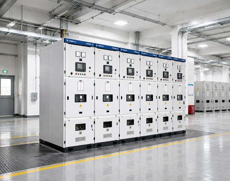
Localized heating often deserves priority because electrical resistance concentrated at a joint can create a hotspot even when total feeder current remains within the expected range. Possible contributors include connection condition, contact wear, contamination, corrosion, surface condition and mechanical alignment.
NFPA 70B maintenance material identifies infrared thermography, permanently mounted thermal sensors and contact-resistance testing as recognized ways to assess electrical connections and terminations. It also emphasizes comparison with manufacturer limits rather than a universal resistance number.
Busbar and Cable Connections
For MV switchgear, compare corresponding bolted joints under similar electrical loading. A hotspot at one connection that does not appear on equivalent phases is stronger evidence of a local issue than a warm bus section that follows overall current.
During an approved outage, qualified personnel can compare the physical condition with the manufacturer’s instructions and the project’s maintenance procedure. The diagnosis should establish the cause before any corrective work is accepted.
Withdrawable Breaker Primary Contacts
A withdrawable breaker adds another interface: the primary disconnect contacts must align and engage according to the equipment design. Abnormal wear, contamination or poor engagement can increase contact resistance. Mechanical position therefore belongs in the thermal investigation as well as the electrical one.
Do not interpret withdrawable construction as permission to remove or insert a breaker under conditions not authorized by the manufacturer. Maintenance access and energized operation are separate questions.
Check Ventilation and the Switchroom Environment
MV switchgear temperature depends on the air surrounding it. IEC 62271-1 defines normal service conditions and includes an indoor ambient range with an upper value of 40°C. Projects outside the declared service conditions require specific consideration rather than silent use of the normal rating.
Document room temperature, ventilation status, nearby heat sources and any change to the installation. New walls, stored materials, filters, cable additions or other equipment can alter the way heat leaves a lineup.
Do Not Treat Open Doors as a Cooling Solution
Leaving MV switchgear doors open changes the verified enclosure condition and can introduce serious safety and environmental risks. If temperature is acceptable only with doors or panels open, treat that observation as evidence that the installed thermal arrangement needs engineering review.
Where the design uses fans or filtered ventilation, confirm which function is expected during normal operation, how loss of cooling is indicated and what operating restriction applies if that cooling is unavailable.
Separate Room Heat from a Local Electrical Hotspot
A useful investigation compares temperature differences, not only absolute temperatures. If three neighboring cabinets rise together as room temperature climbs, the room or shared airflow deserves attention. If one terminal rises far above equivalent joints while ambient conditions remain stable, a local electrical cause becomes more plausible.
This distinction matters because the corrective actions are different. Adding ventilation will not repair a high-resistance contact, while replacing a sound connection will not solve a switchroom that operates outside the equipment’s approved ambient conditions.
For MV switchgear with both symptoms, treat them as two workstreams. Correcting one may reduce temperature but leave the other unresolved.
Use Infrared Thermography as Evidence, Not a Verdict
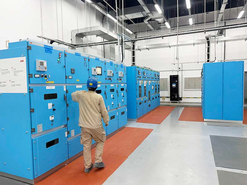
Infrared thermography is valuable for comparing surface temperatures and detecting patterns, but a thermogram is not self-explanatory. ISO 18434-1 provides guidance on thermography procedures, including reflected apparent temperature, emissivity and data interpretation.
For MV switchgear trending, record the electrical load at the time of the image and compare equivalent components under similar conditions. Surface material, viewing angle and reflected energy can distort apparent temperature.
Trend Comparable Points
A single image is useful for screening. A repeated measurement at a defined point, combined with current and ambient data, is more useful for determining whether a condition is stable or worsening.
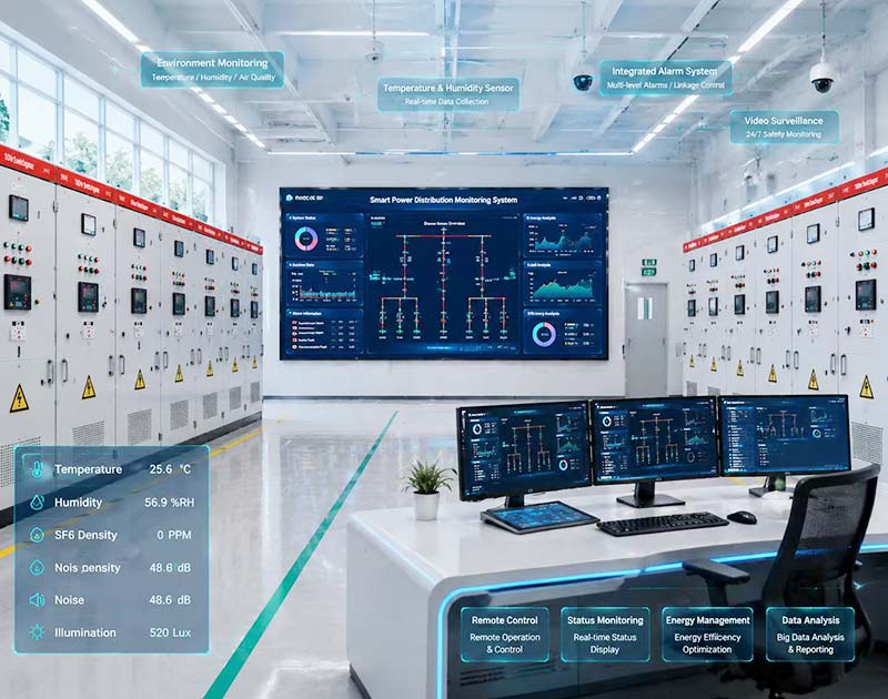
Where permanent temperature sensors are specified, define the sensor locations, alarm logic, communications interface and responsible response. Monitoring does not remove the need to understand the electrical cause of an abnormal trend.
Do Not Confuse Overheating with Partial Discharge
Heat and partial discharge are different phenomena, although one asset can show evidence of both. Partial discharge relates to localized dielectric activity, while thermal hotspots often involve current, resistance or cooling. Do not use one diagnostic method as proof of the other.
For MV switchgear showing insulation damage, unusual sound, ozone-like odor or other dielectric concerns, have the responsible engineer determine whether a partial-discharge assessment is required. Keep those findings separate from the thermal diagnosis until evidence links them.
This separation prevents a common maintenance error: replacing a hot connection and assuming the insulation system has automatically been cleared for continued service.
Compare the Equipment with Its Approved Configuration
Modifications can change the thermal behavior of MV switchgear. A different breaker, conductor arrangement, current transformer, ventilation opening or cable termination can alter losses or airflow. Review changes against the documentation supporting the original design.
IEC 62271-200 addresses temperature-rise testing as part of the metal-enclosed assembly framework. For a modified configuration, ask whether the existing verification evidence still applies and what technical assessment supports the change.
This is especially important when a series catalogue contains multiple current and fault ratings. Do not apply the highest published value to every KYN28A-12 panel. Request a model-specific rated-data sheet and supporting documents for the actual assembly.
Example: One Feeder Runs Hot but the Bus Does Not
Consider a hypothetical factory with several MV switchgear transformer feeders. During a planned thermographic survey, one feeder’s cable-side connection appears markedly hotter than the equivalent connections on the other feeders. The feeder current is similar to the others and the room temperature is stable.
This pattern does not prove a loose connection, but it makes a local resistance or interface issue a reasonable investigation priority. The useful evidence package includes the thermal image, load at the time of measurement, comparison with equivalent phases, previous trend data and the relevant connection drawing.
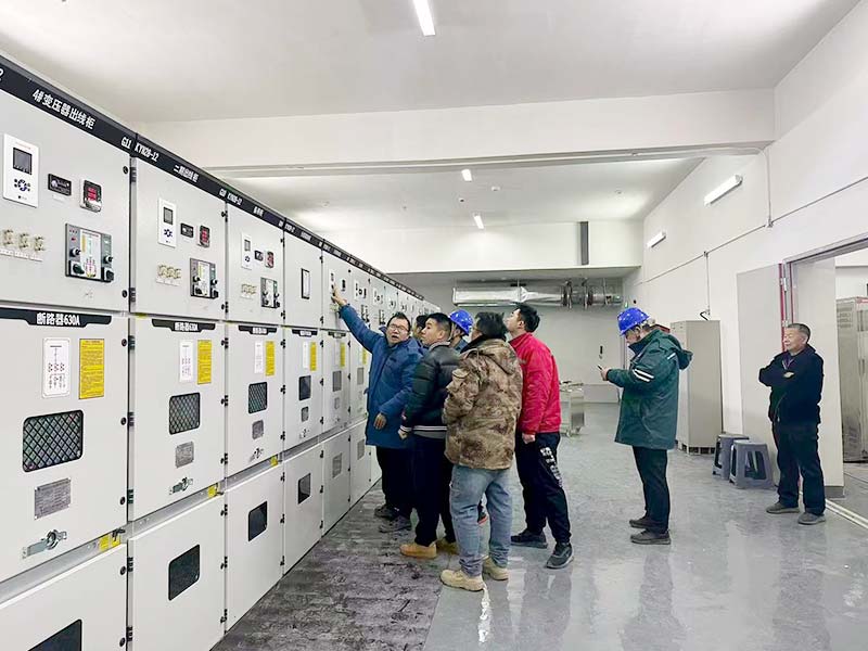
During an approved outage, qualified personnel can examine the connection and perform the manufacturer-approved checks required by the maintenance program. If the condition is corrected, repeat comparable measurements under similar loading before closing the issue.
Now consider a second scenario: all feeder compartments trend warmer during a period when the switchroom air temperature also rises significantly. That pattern shifts attention toward ambient and ventilation conditions. The same word, overheating, can therefore lead to very different engineering questions.
Build a Better MV Switchgear Overheating Investigation Record
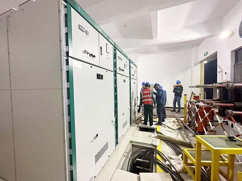
A structured record helps engineers decide whether the issue is loading, connection condition, environment or measurement. It also makes supplier discussions more efficient.
| Information to record | Why it matters |
|---|---|
| Panel and feeder identification | Connects the symptom to the correct drawing and configuration |
| Phase currents and operating mode | Shows the electrical duty present during the event |
| Ambient and compartment temperatures | Separates room conditions from local heating |
| Thermal images with load and time | Supports comparison and trend analysis |
| Recent equipment or cable changes | Identifies configuration changes that may affect heat or airflow |
| Alarm and protection history | Shows whether the event coincided with another abnormal condition |
| Maintenance and previous test records | Provides baseline condition and recurring-fault evidence |
Keep the record tied to drawing revisions and equipment identifiers. A strong MV switchgear diagnosis depends on comparable evidence, not on one isolated temperature value.
How to Reduce Overheating Risk in New MV Switchgear Projects
Prevention starts with correct project inputs. Provide the continuous current, credible operating modes, fault data, room environment, cable interfaces and expected expansion before the switchgear is finalized.
For MV switchgear in a factory, coordinate transformer feeder currents with the room thermal design and the planned maintenance access. If monitoring is required, define which connections or compartments need temperature indication and how alarms will be handled.
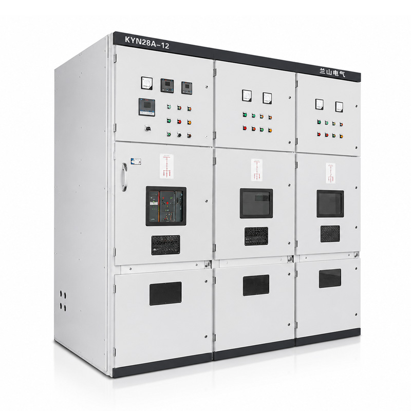
Lanshan’s KYN28A-12 medium voltage switchgear uses a withdrawable vacuum circuit-breaker arrangement with separated functional compartments. Request the exact current rating, short-time withstand data, enclosure arrangement and verification documents for the proposed configuration rather than applying broad series values automatically.
For procurement background, see 7 factors to consider before buying medium voltage switchgear.
What to Send Lanshan for a Thermal or Replacement Review
If an existing MV switchgear lineup is developing repeated thermal concerns, send the single-line diagram, equipment model, feeder duties and fault-level data together with the temperature history. Include photographs and thermal records that can be shared safely.
For a replacement or expansion project, add the room layout, cable arrangement, site ambient conditions and required monitoring functions. State whether the problem is one hotspot, a whole compartment, or the complete lineup.
A useful technical review should identify what data remain missing and what project conditions need confirmation. It should not assume that replacing the cabinet alone solves a room, loading or connection problem.
Conclusion
MV switchgear overheating should be treated as an evidence problem before it becomes a replacement decision. Compare load, ambient conditions and equivalent components, then distinguish a local high-resistance hotspot from system-wide thermal stress.
Use approved inspection methods, preserve measurement context and keep internal work within a properly isolated maintenance procedure. Contact Lanshan Electric with your single-line diagram, fault data and temperature records to discuss a suitable MV switchgear configuration or replacement review.
FAQ
What is the most common cause of MV switchgear overheating?
There is no single universal cause. High current, abnormal connection resistance, contact condition, high ambient temperature and restricted cooling are all credible possibilities. The thermal pattern and operating data should determine which explanation receives priority.
Can a loose connection make switchgear hot even below rated current?
Yes. A local increase in resistance can create concentrated I²R heating even when overall feeder current is not excessive. The condition should be evaluated under an approved maintenance program using evidence appropriate to the connection and equipment.
Is infrared thermography enough to diagnose MV switchgear overheating?
No. Thermography is valuable for detecting and trending surface-temperature anomalies, but interpretation depends on load, ambient conditions, emissivity, reflected temperature and comparable equipment. Use it as part of a broader condition assessment.
Should MV switchgear doors be opened to improve cooling?
No. Operating with doors or panels open can change the verified enclosure condition and create serious safety risks. If normal operation requires an altered enclosure, the cooling and equipment configuration need engineering review.
What data should I send when reporting switchgear overheating?
Send the panel and feeder identification, phase currents, ambient conditions, alarm history, thermal images with timestamps, recent modifications and available maintenance records. Add the single-line diagram and rated-data sheet so the reviewer can compare the symptom with the actual configuration.