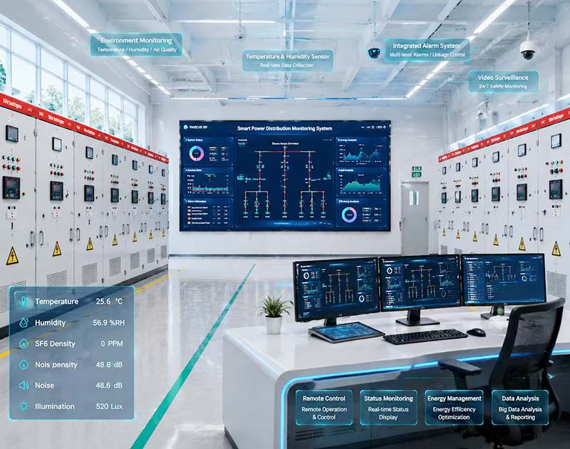
A power monitoring system should begin with operating decisions, not a list of meters. If the maintenance team needs to know why a feeder tripped, the system must preserve the right event data. If management wants to reduce peak demand, the system must measure demand at points that explain where it is created.
For industrial facilities, the most useful design question is simple: what electrical decision will each measurement support? This guide explains how to define monitoring points, measurement functions, communications, alarms and data ownership without assuming that every factory needs the same software platform.
Start with Decisions, Not Devices
Before choosing a meter or communication protocol, write down the decisions the power monitoring system must support. Common objectives include verifying incoming demand, locating abnormal feeder loading, checking power factor, identifying repeated voltage disturbances and allocating energy use between production areas.
Each objective needs a defined measurement location and time resolution. Monthly energy from the utility meter cannot explain a ten-second voltage dip. A high-resolution recorder on one production line cannot allocate annual energy consumption to every workshop. The measurement architecture should match the question.
In a power monitoring system, keep monitoring separate from control. Reading breaker status is not the same as issuing a remote open or close command. Where control is required, define authorization, interlocks and the party responsible for the control logic as a separate project function.
Build a Power Monitoring System Point List from the Single-Line Diagram
Mark the proposed power monitoring system points directly on the electrical single-line diagram. Start at the incoming supply, then move through transformers, main low-voltage boards and the feeders that represent important production loads.
Do not install identical instrumentation everywhere without a reason. The main incomer may need demand, energy and power-quality information; a large motor feeder may need current and operating status; a tenant or production-area feeder may need energy allocation. The required functions can differ even when the devices communicate over the same network.
| Monitoring point | Typical questions to answer | Possible measurements |
|---|---|---|
| Utility or plant incomer | What is the facility importing and when does peak demand occur? | Voltage, current, kW, kvar, kVA, power factor, demand, energy |
| Transformer secondary | How heavily is each transformer loaded? | Current, kW/kVA, power factor, energy, temperature signals where available |
| Main LV bus section | How is load shared between sections? | Current, kW, demand, breaker status |
| Large process feeder | Is the load behaving differently from normal production? | Current, kW, power factor, energy, status |
| Critical utility feeder | Did the event affect cooling, air or pumping services? | Current, voltage, status, alarms |
| Selected sensitive load | Are voltage disturbances correlated with process trips? | Event or power-quality data where justified |
Use this power monitoring system point list as a functional schedule. It gives the panel manufacturer, meter supplier and automation integrator a common reference and prevents a vague request for “smart monitoring” from becoming several incompatible assumptions.
Power Monitoring System Measurements: Choose the Right Electrical Quantities
A basic power monitoring system often measures voltage, current, active power, reactive power, apparent power, power factor and energy. Demand functions can help facilities understand sustained peaks rather than only instantaneous load.
For low-voltage power metering and monitoring devices, IEC 61557-12 defines requirements for power metering and monitoring devices used in industrial and commercial applications. The standard also distinguishes this class of device from dedicated power-quality instruments. See the official IEC 61557-12 publication for scope and current amendment status.
Specify the accuracy or performance needed for the actual use. Internal operational monitoring, cost allocation and contractual billing can require different evidence. Do not describe every internal meter as a revenue meter unless the applicable metering and regulatory requirements are actually met.
Current and Voltage Are the Foundation
Current shows how each phase is loaded, while voltage establishes the electrical condition at the measurement point. The power monitoring system should preserve phase-by-phase values where imbalance matters instead of reporting only one average number.
Define the CT ratio, accuracy requirements and connection responsibility for current measurement. A meter can only report useful values when its sensing arrangement, scaling and wiring match the installed circuit.
Power Factor Needs Context
Power factor is most useful when it is linked to load and time. A low value at very light load can have a different operational meaning from the same value during full production. Record kW and kvar alongside power factor so the facility can distinguish low load from high reactive demand.
Separate Routine Monitoring from Power Quality Monitoring
A general power monitoring system can show trends in voltage, current, demand and energy, but that does not automatically make every installed meter a power-quality instrument. Dedicated power-quality monitoring involves defined measurement methods, event capture and instrument performance.
IEC 62586-1 specifies product and performance requirements for power-quality instruments whose measurement methods are defined by IEC 61000-4-30. IEEE 1159-2019 provides recommended practice for monitoring and interpreting power-system disturbances.
For a factory that experiences unexplained drive trips, controller resets or voltage-sensitive process interruptions, define the events that must be captured. Voltage sag, swell, interruption, transient and harmonic requirements should not be replaced by a generic “power quality” checkbox.
Decide Where Event Capture Is Worth the Cost
Install event-capable monitoring where the data can distinguish between possible causes. The plant incomer may show whether a disturbance arrived from upstream. A selected production bus may show whether the event was local to that section. Placing advanced instruments at every small feeder may add data without improving diagnosis.
Set Sampling, Logging and Demand Intervals Deliberately
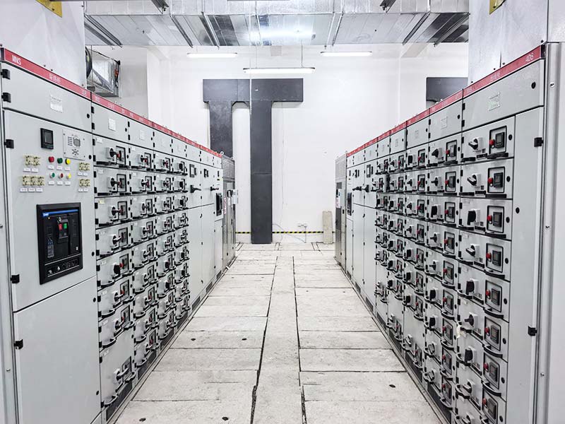
A power monitoring system needs more than a list of parameters; it needs a time model. Define how often values are sampled, how often trends are stored, how demand is calculated and how long data are retained.
For energy management, 15-minute or another agreed demand interval may be useful depending on the facility and utility arrangement. For equipment troubleshooting, much faster event data may be necessary. Do not use a slow trend interval to claim that a short disturbance did not occur.
Synchronize device time when events from several panels need to be compared. Otherwise, a trip in one feeder and a voltage change at the incomer may appear unrelated simply because their clocks differ.
Power Monitoring System Alarms Must Lead to an Action
An alarm should identify a condition, threshold, delay and responsible response. The power monitoring system should not create dozens of alarms that operators cannot interpret.
For example, a high-current alarm may require a defined percentage of a reviewed circuit loading limit for a specified duration. A low power-factor alarm may only be useful above a minimum active-load threshold. A communication-loss alarm should identify which meter or gateway stopped reporting.
| Alarm type | Useful definition questions | Avoid |
|---|---|---|
| High current | Which circuit limit? How long must it persist? | One generic ampere threshold for every feeder |
| Low voltage | At which measurement point and duration? | Alarm based on one instantaneous sample |
| Low power factor | At what minimum kW load? | Alarm during near-zero load |
| Demand warning | Which demand window and target? | Comparing instantaneous kW to a demand limit |
| Communication loss | How long before declaring offline? | Treating a network fault as an electrical fault |
| Temperature input | Which sensor and equipment limit? | Using an unverified generic temperature threshold |
Record who owns each alarm. A technically correct alarm has little operational value if nobody is responsible for acknowledging, investigating and closing it.
Power Monitoring System Communications: Define the Interface
The power monitoring system should define how data move from each field device to the owner’s system. “RS485 available” is incomplete unless the protocol, register map, addressing rules and gateway responsibility are also defined.
Modbus is widely used for industrial device communications. The Modbus Organization publishes the Modbus Application Protocol and implementation guidance for serial and TCP/IP use. A protocol name alone, however, does not guarantee that two devices expose the same data model or register addresses.
Request a register list or device communication manual for every meter that will be integrated. State who configures addresses, baud rates, gateways and network settings. Identify whether data are read-only or whether write functions are permitted.
Do Not Call RS485 the Protocol
RS485 describes an electrical communication interface, not the complete application protocol. A device may use an RS485 physical layer with Modbus RTU or another protocol. The procurement specification should identify both the interface and the protocol.
Keep Monitoring and Cybersecurity Responsibilities Visible
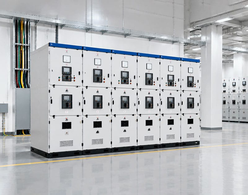
Once the power monitoring system connects field devices to a plant network, the project also has a cybersecurity boundary. IEC 61557-12 explicitly notes that its PMD requirements do not address cybersecurity, so meeting the metering standard does not close the network-security review.
Define network segmentation, remote-access policy, account ownership, password management and responsibility for firmware or gateway updates with the facility’s IT/OT team. Where Modbus Security is relevant, the Modbus Organization describes a TLS-based security protocol, but its use still requires system-level design and compatible devices.
Do not promise secure remote operation merely because a meter supports Ethernet. Monitoring, remote access and remote switching are separate functions with different consequences.
Decide What Belongs in the Panel and What Belongs in the Platform
A practical power monitoring system has at least three layers: sensing and meters in the electrical equipment, communications that transport data, and a software layer that stores or visualizes it. Assign each layer to a named party.
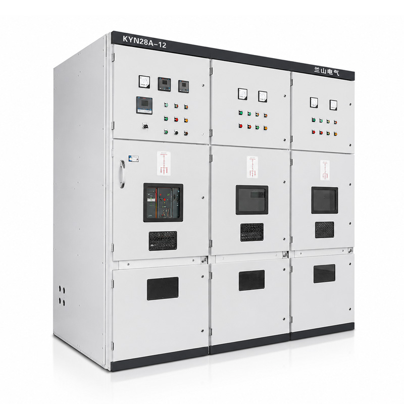
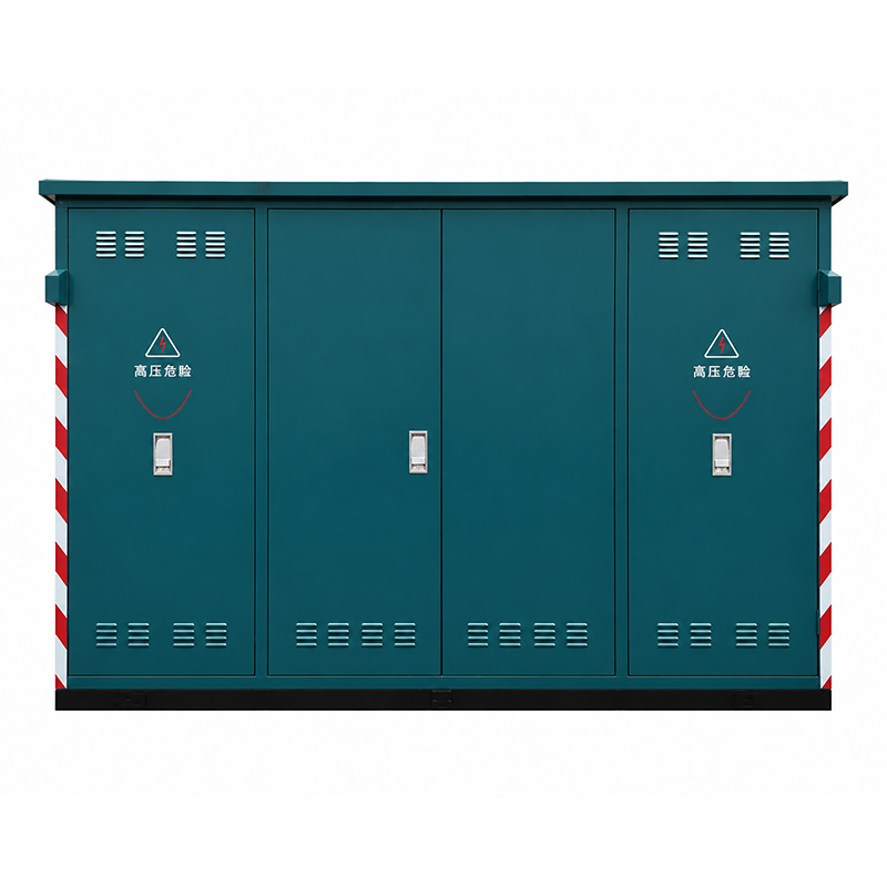
Lanshan’s integrated distribution box can be discussed with optional monitoring and communication requirements as part of a project-specific configuration. The project should confirm the exact meter, signals and interface rather than assuming that the distribution box includes a particular EMS, SCADA or cloud platform.
If the owner already has a supervisory platform, provide its interface requirements and approved device list where applicable. The panel supplier can then confirm which field devices and communication provisions fit that integration plan.
Use a Point List and Responsibility Matrix in the RFQ
A power monitoring system RFQ should contain a point list, a communication architecture and a responsibility matrix. This is more useful than specifying a brand-neutral phrase such as “complete intelligent monitoring.”
| RFQ item | Information the buyer should provide | Supplier/integrator response |
|---|---|---|
| Measurement point | Panel and feeder reference | Proposed device and connection |
| Measured values | Required electrical quantities | Available functions and accuracy/performance |
| Status signals | Breaker or alarm points required | Source contact or communication object |
| Protocol | Required protocol and physical interface | Supported interface and documentation |
| Data interval | Trend, demand and event needs | Available logging or upstream requirements |
| Time synchronization | Required reference and accuracy | Supported method or gateway dependency |
| Platform interface | Existing EMS/SCADA/BMS requirements | Data handoff boundary |
| Testing | Points and communications to prove | Factory/site test responsibility |
Give every point a unique tag. The same tag should appear in the single-line diagram, panel schematic, meter schedule and integration database. This reduces commissioning errors and makes future troubleshooting easier.
Example: Monitoring a Factory with Two Transformers
Consider a hypothetical factory with two distribution transformers feeding separate low-voltage bus sections. Production lines operate mainly on one section, while cooling and compressed-air utilities are concentrated on the other. The sections can be tied under an approved operating arrangement.
A useful power monitoring system would not simply place one meter on each transformer. It would measure both incomers, selected production feeders and the common utility feeders. Breaker status at the bus coupler would be included so engineers can interpret load transfer correctly.
Suppose the plant sees a new monthly demand peak. Incomer trends show that total kW increased when the bus tie was closed, while the compressed-air feeder also increased sharply. The monitoring architecture now gives the team two useful facts: the operating topology changed, and one shared utility contributed materially to the peak.
Without the coupler status and feeder measurements, the same event might look like unexplained transformer loading. The value of a well-designed power monitoring system comes from placing measurements around decisions and system topology, not from collecting the largest possible number of variables.
Power Monitoring System Acceptance Testing
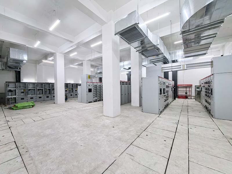
Monitoring functions should appear in the factory and site test plans. At the panel factory, confirm meter model, ratios, wiring, communications settings and the selected indications that can be demonstrated without the complete site network.
At site, verify end-to-end data where the external platform and network are available. Check that the displayed feeder identity, engineering units, scaling and status match the approved drawings. A successful ping or serial connection is not proof that the data mapping is correct.
For the power monitoring system, agree how lost communications, invalid measurements and time-sync failure will be tested. Record final network addresses and register maps in the handover documents.
Power Monitoring System Mistakes to Avoid
The first mistake is collecting data without defining a use. This produces dashboards that look complete but do not answer maintenance or energy questions.
The second is mixing power-quality requirements with routine metering. If sag capture or waveform evidence is needed, specify the measurement function and appropriate instrument performance rather than expecting every multifunction meter to provide it.
The third is leaving communication integration until commissioning. A meter can measure correctly and still fail the project because the protocol, register map or gateway was never agreed.
The fourth is treating a communication interface as permission for remote control. Keep read-only monitoring, supervisory commands and protective functions separated in the design and acceptance documents.
Finally, avoid assuming that the electrical equipment manufacturer supplies the owner’s entire software ecosystem. Define the power monitoring system boundary clearly and ask each party to confirm what it will deliver.
What to Send Lanshan for a Monitoring-Ready Distribution Configuration
Send the single-line diagram, panel schedule and monitoring point list together. Identify the electrical quantities, status signals, communication protocol and external system that will receive the data.
Where a project uses Lanshan low voltage switchgear or distribution boxes, request a configuration-specific meter and interface schedule. Confirm device models, CT requirements, communication wiring and terminal provisions before manufacture.
If the owner needs event or power-quality monitoring, state that requirement separately. Share the expected event types, measurement points and data-export requirements so the correct instrument class can be reviewed rather than inferred from the phrase “smart monitoring.”
Conclusion
A good power monitoring system is a measurement architecture tied to operating decisions. Define where to measure, what to record, how quickly the data must be captured and who owns the communications and software interfaces.
For a project-specific review, contact Lanshan Electric with your single-line diagram, point list and interface requirements. The configuration discussion can then focus on confirmed meters, signals and communication provisions instead of an undefined smart-distribution promise.
FAQ
What should a factory power monitoring system measure?
At minimum, measure the quantities needed for the facility’s decisions. Typical points include voltage, current, active and reactive power, apparent power, power factor, demand and energy. Critical feeders may also need breaker status, alarms or event data depending on the objective.
Is a power monitoring system the same as a power quality system?
No. Routine power monitoring can track load, demand and energy, while dedicated power-quality monitoring may require defined event capture and instrument performance under IEC 62586 or practices such as IEEE 1159. Specify the functions separately.
Is RS485 enough to integrate a meter with SCADA?
No. RS485 is an electrical interface. The project also needs the application protocol, device address settings, register map and integration responsibility. Modbus RTU is one common protocol carried over RS485, but compatibility still needs to be verified.
How many meters should an industrial facility install?
There is no universal number. Place meters where their data can explain demand, equipment loading, energy use or disturbances. Start with the incomer and major distribution boundaries, then add selected feeders where the operational value justifies the additional instrumentation.
Can Lanshan supply a complete EMS or SCADA platform?
The current public product information supports project-specific monitoring and communication options in electrical distribution equipment, but it does not establish a complete proprietary EMS, SCADA or cloud platform. Confirm the required field devices and interfaces with Lanshan and define the external platform separately.