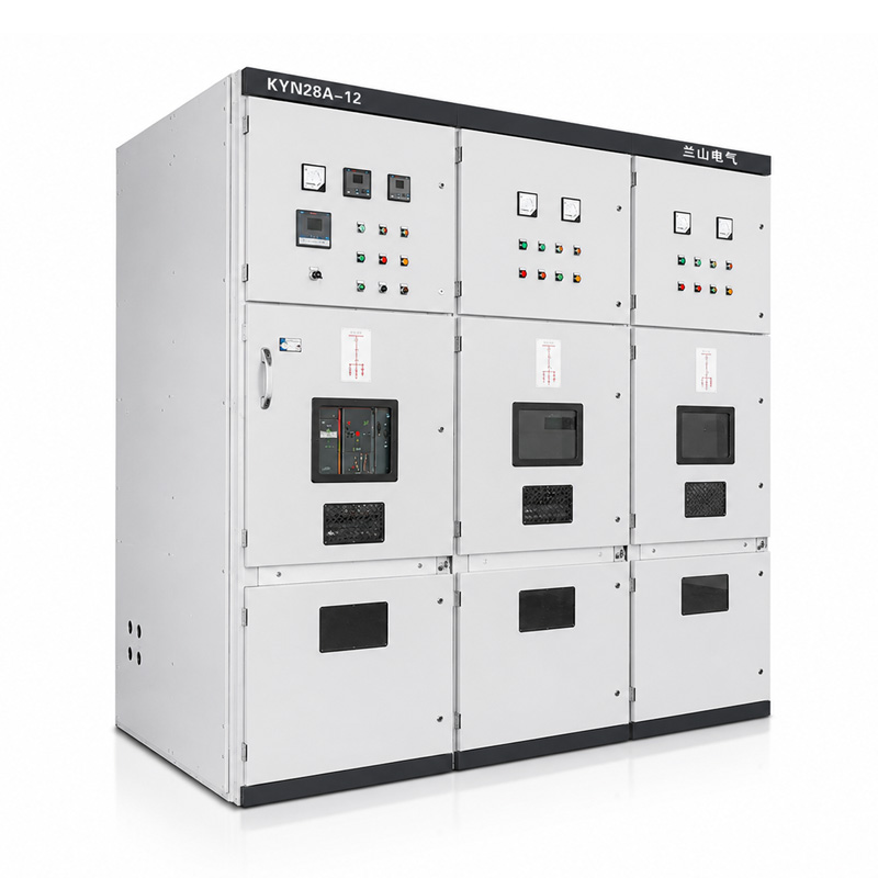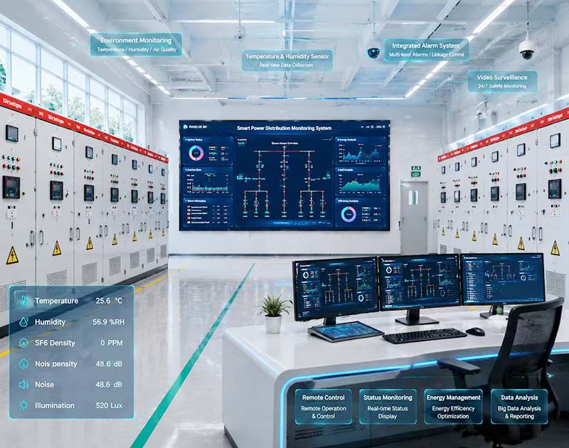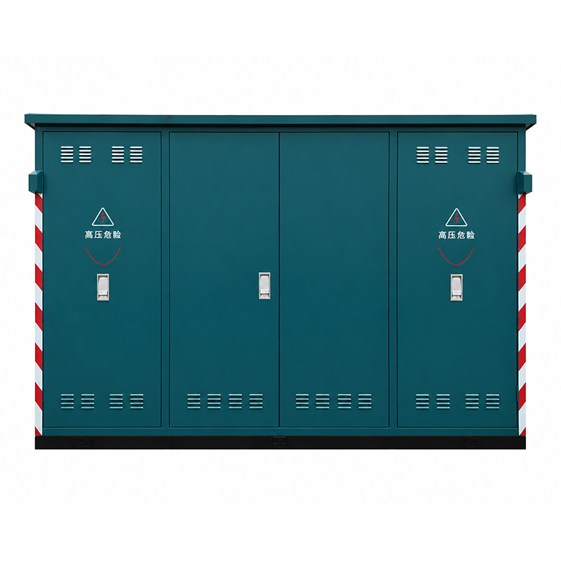
A ring main unit is easier to specify when you follow the current path rather than count the compartments. Which device carries the ring current? Which one clears a transformer fault? What tells the operator that a fault has passed through a cable?
Those are different functions, even when the equipment shares one enclosure. This guide explains the main components through their electrical duties, then shows how they work together in a practical distribution scenario.
Table of Contents
What Does a Ring Main Unit Do?
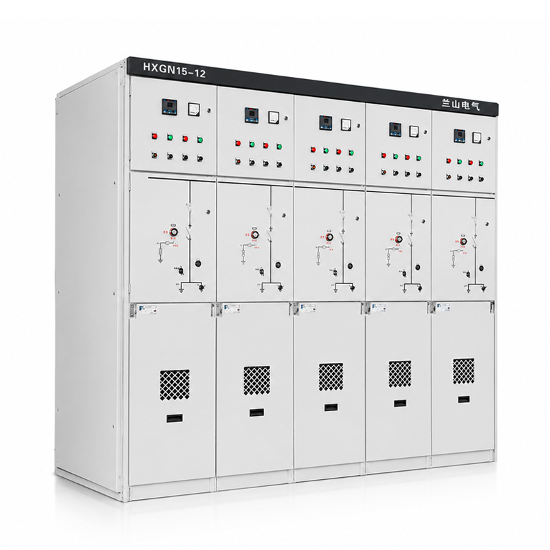
A ring main unit, or RMU, is a compact medium-voltage switchgear assembly used to connect, section and protect parts of a distribution network. A familiar arrangement has two ring-cable connections and a protected transformer branch, although other configurations are possible.
The ring describes the network arrangement, not a circular busbar inside the cabinet. Distribution networks can operate with a normally open point, leaving an alternative path available for approved restoration after a fault. This arrangement appears in published distribution-network design guidance.
A ring main unit does not automatically provide uninterrupted supply. Restoration depends on the network, available capacity, protection and switching arrangements. Specify those expectations separately from the cabinet itself.
For the wider equipment context, see Lanshan’s introduction to how medium voltage switchgear works.
Ring Main Unit Components at a Glance
The table separates the main duties before examining the details. Some components are alternatives or project options; not every ring main unit contains every item listed. The switching and protection distinctions follow the applicable switch, switch-fuse and circuit-breaker standards.
| Component | Main function | What buyers should verify |
|---|---|---|
| Ring switch or switch-disconnector | Switches the ring circuit within its rated duties | Load-breaking, making and isolation capabilities |
| Transformer protection device | Clears specified faults on the transformer feeder | Approved switch-fuse combination or breaker scheme |
| Busbars | Connect the functional units electrically | Current rating and short-circuit withstand |
| Earthing switch | Connects a designated circuit section to earth | Earthing location, rating and interlocking |
| Cable terminations | Connect external cables to the primary circuit | Cable and interface compatibility |
| Current transformers or sensors | Supply signals for protection or measurement | Output, accuracy and relay compatibility |
| Protection relay | Evaluates electrical conditions and issues a trip command | Functions, settings and tripping supply |
| Voltage detecting system | Indicates the voltage condition at its connection point | System type and permitted use |
| Fault passage indicator | Indicates that qualifying fault current passed its sensing point | Detection behavior, directionality and reset method |
| Operating mechanism and auxiliaries | Actuate devices and provide status or control interfaces | Manual, motorized and remote-control scope |
Use this as a functional checklist, not a universal bill of materials. The sections below explain the limits behind each description.
Describe the Circuit Arrangement, Not Just the Number of Ways
For a project needing two ring connections and one transformer branch, write those functions explicitly. A request for a “three-way RMU” should still include a diagram identifying the device in each way. State whether any quoted metering function occupies an additional module or is incorporated into another unit.
Also identify the expected future addition. An unused feeder, an empty panel position and an extensible bus interface are different proposals. Ask which expansion is included, what equipment it would require and which parts would need to be taken out of service. This makes the component schedule useful beyond the first installation.
Ring Switches: Load Breaking Is Not Fault Clearing
Ring feeders often use switch-disconnectors. Their switching duty includes interrupting specified load currents; their disconnector function provides a defined isolating condition. A plain disconnector must not be treated as a load-break switch. IEC 62271-103 addresses switching duties, while IEC 62271-102 addresses disconnectors and earthing switches.
For a ring main unit, distinguish continuous current, short-circuit making current and short-time withstand current. Making a circuit and interrupting its fault current are different capabilities. A making or withstand rating does not demonstrate short-circuit breaking capability.
For example, an offer stating only “630 A ring switch” leaves the fault duties unresolved. Ask what clears a fault on that circuit and request the relevant device ratings. The illustrative current value is not a specification for every RMU.
This distinction prevents a common procurement mistake: treating every switching device on the single-line diagram as a circuit breaker.
Transformer Protection: Switch-Fuse or Circuit Breaker?
The transformer branch of a ring main unit needs a defined protection arrangement. Two established approaches are a coordinated switch-fuse combination and a circuit breaker operated by a protection scheme. They are alternatives to evaluate, not interchangeable labels.
Switch-Fuse Combinations
A switch-fuse combination joins switching functions with current-limiting fuses. IEC 62271-105 treats the combination as a functional assembly with specified making and breaking capabilities. Evaluate the approved combination rather than selecting a fuse solely because it fits the holder.
Ask for the selected fuse characteristics, transformer compatibility and coordination basis. Where fuse strikers operate the switch, confirm that arrangement in the approved documentation. Do not assume any fuse of the same nominal current is an acceptable substitute.
Circuit Breakers and Relays
A breaker-based ring main unit uses a device with specified interruption capability, supported by the required protection and trip circuit. IEC 62271-100 covers AC circuit breakers and their making-breaking tests.
Compare the protection functions your project requires, not just the presence of a relay. Define the transformer duty, available fault current and coordination with upstream and downstream protection before approving the scheme.
Busbars and Insulation: The Current Path Inside
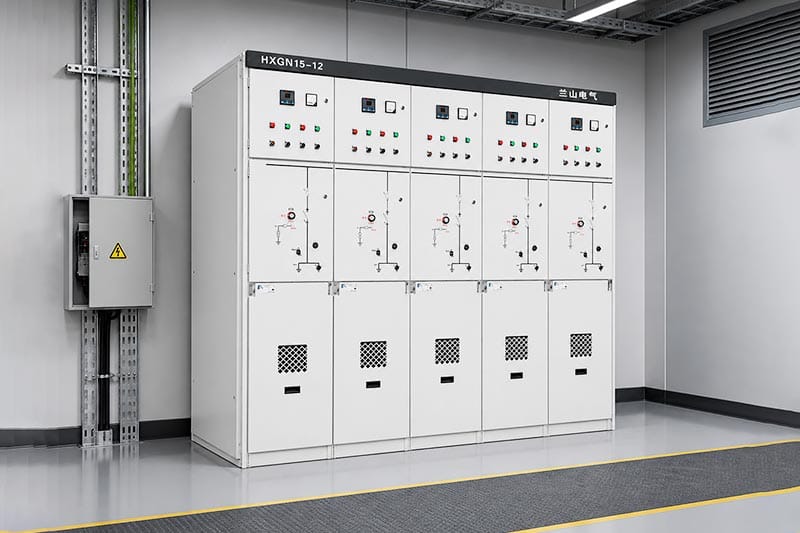
Busbars provide the common electrical connection between functional units. In a ring main unit, their rating must be considered separately from the transformer branch rating; the two need not be identical. Published RMU equipment schedules illustrate that distinction.
For procurement, request the busbar continuous-current rating, short-time withstand current and its duration. Confirm which values apply to the complete offered arrangement and its installation conditions.
Also separate the insulation system from the interruption technology. A description such as “vacuum circuit breaker” does not, by itself, identify the insulation surrounding the busbars and cable interfaces. Specify both characteristics instead of trying to infer one from the other.
For a gas-filled ring main unit proposal, ask what monitoring and pressure-relief provisions apply. Do not assume a gas system, a particular gas or an environmental claim from the RMU name alone.
Earthing Switches and Interlocks Have Different Jobs
An earthing switch connects a defined part of the circuit to earth. Interlocks restrict incompatible device positions or access conditions. These functions support an engineered operating arrangement; they are not substitutes for an authorized safe-working procedure.
For the ring main unit drawing, identify what is earthed: the cable side, another circuit section or a separately defined connection. Ask the supplier to explain which doors and mechanisms are interlocked and what the position indicators represent.
A three-position device can combine connected, isolated and earthed positions, but the exact arrangement must be read from its documentation. Do not assume that an open breaker alone provides the required isolation for work.
Only qualified, authorized personnel should operate or access medium-voltage equipment under applicable rules. OSHA’s electrical work-practice requirements illustrate the distinction between an operating indication and verified de-energization; the relevant local requirements govern.
Cable Compartments: Where Installation Details Matter
The cable compartment connects the ring main unit to the actual network. Its usefulness depends on the termination arrangement, not simply on whether the door opens conveniently.
Provide cable voltage class, conductor size and material, core arrangement and outside diameter. Ask for the interface drawing, compatible termination details, support arrangement and required bending space. Include screen-earthing connections and any specified surge-protection accessories in the review.
For a ring main unit supplied separately from its cables, assign responsibility for selecting and supplying the termination kits. Keep the switchgear interface and cable-accessory selection coordinated. Resolve the termination arrangement for each feeder rather than treating the main rating plate as a connection drawing.
A compact cabinet is not automatically suitable for a restricted cable trench. Resolve the cable approach and connection space before approving the foundation or ordering accessories.
CTs and Relays: Follow the Complete Trip Chain
Current transformers, or CTs, provide signals for measurement and protection. IEC 61869-2 covers inductive CTs used with measuring instruments and protective devices. Other sensor technologies require their own applicable specification.
In a breaker-protected ring main unit, follow the complete chain: current measurement, relay decision, trip output, trip mechanism and breaker interruption. A suitable relay cannot compensate for an incompatible sensor or an undefined tripping supply.
Check More Than the CT Ratio
For conventional protective CTs, review accuracy requirements, burden and fault-current performance. The IEC application guide for protection CTs specifically addresses their behavior under short-circuit conditions.
Confirm the signal expected by the relay and who supplies the wiring, settings and test records. For a ring main unit using self-powered protection, request the documented operating limits and tripping arrangement; do not assume that every relay function remains available without auxiliary power.
The practical acceptance question is whether the supplied sensing and tripping system performs the agreed protection functions as a coordinated arrangement.
Voltage Indication, Fault Indication and Metering
These functions answer different questions. Treating them as one generic “monitoring system” leaves important requirements unresolved.
Voltage Detecting and Indicating Systems
IEC 62271-213 covers voltage detecting and indicating systems connected to high-voltage equipment through a coupling system. The indication relates to the monitored connection point; it is not a certificate that the entire ring main unit is safe to touch.
Specify the system type and its permitted use. A dark indication alone must not replace the approved method of establishing a safe condition.
Fault Passage Indicators
A fault passage indicator provides information about fault current passing its sensing location; it is not the device that interrupts that current. IEEE 495 addresses testing of faulted circuit indicators for distribution systems.
Ask whether directional indication is needed and how indication is retained or reset. Identify which ring main unit circuits are monitored rather than assuming one indicator covers every branch.
Metering Equipment
Metering may require dedicated CTs and voltage transformers with agreed accuracy and output characteristics. IEC 61869-3 covers inductive voltage transformers used for measurement and protection. A voltage-presence indicator is not a replacement for the specified metering arrangement.
Operating Mechanisms and Remote-Control Options
The operating mechanism moves the primary switching device. Motor operation, auxiliary contacts and remote-command wiring are separate provisions to specify; utility procurement documents list these interfaces explicitly.
For a remotely operated ring main unit, define the actuator supply, local/remote selection, position feedback and response to loss of control power. State which commands must be blocked under particular conditions.
A motorized ring main unit is not automatically an autonomous restoration system. The controller, communications, operating logic and network permissions need their own scope.
Agree functional demonstrations before acceptance: command issued, permitted action completed, correct position returned, and prohibited action blocked. Record who verifies the external controller interface at site rather than assuming factory wiring completes the integration.
How the Components Work Together During a Fault
Consider a hypothetical industrial estate with several substations connected along an open-ring network. One ring main unit has two ring feeders and a protected transformer branch. This is an explanation of component roles, not a switching instruction.
If a ring cable develops a fault, the assigned upstream protective device interrupts the fault current. Indicators may help identify the affected section. An approved restoration arrangement can then permit healthy sections to be resupplied, provided the alternative route and protection remain suitable.
The important distinction is responsibility. A ring switch provides its specified switching and isolation functions; it does not become a fault-interrupting breaker because a fault occurred nearby.
Now consider a fault on the transformer branch instead. The branch protection is intended to clear faults within its assigned duty, with selectivity determined by the protection design. Ring-cable protection and transformer-feeder protection therefore require different checks.
Before purchase, ask the designer to identify the detecting and interrupting devices for each credible fault location. That exercise reveals more than a generic promise of “reliable distribution.”
Match the RMU Configuration to the Project
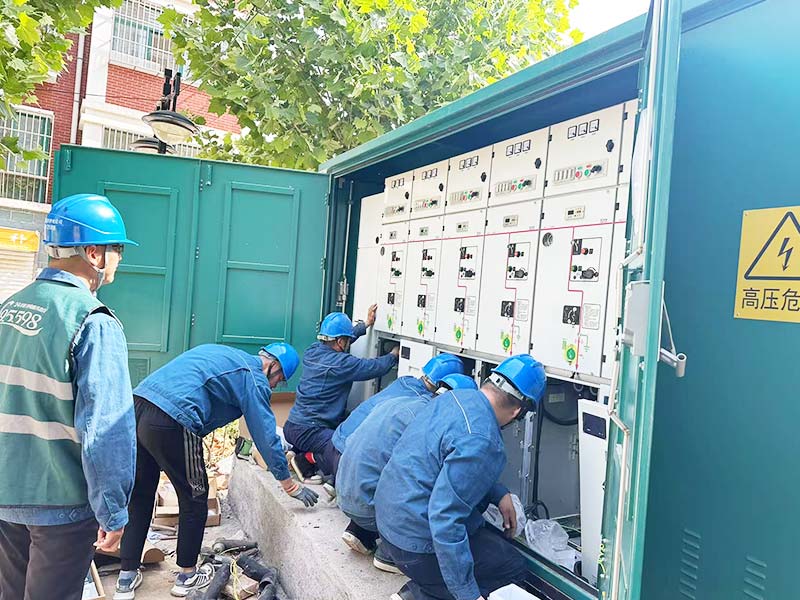
When comparing ring main unit components, map every proposed device to the single-line diagram and require its relevant ratings. Keep continuous-current ratings, short-circuit duties and internal arc performance in separate fields.
IEC 62271-200 applies to relevant metal-enclosed assemblies above 1 kV through 52 kV. Request evidence for the offered assembly and declared characteristics, not merely certificates for individual components. The required edition and project acceptance criteria should be agreed explicitly.
Lanshan’s HXGN15-12 ring main unit describes configurable incoming, outgoing, transformer-protection and metering functions, with switching, busbar, cable and mechanism compartments.
Request a project-specific datasheet confirming the exact insulation system, switching devices, feeder scheme and test documentation. Do not apply a broad series range to a particular HXGN15-12 configuration without confirmation.
Send the network diagram, transformer ratings, fault-level information, cable details and monitoring requirements together. This gives the configuration review a consistent technical basis.
Conclusion
A ring main unit works as a coordinated assembly, not a collection of interchangeable parts. Ring switches, transformer protection, earthing devices and indicators each have a defined job. The right selection makes those duties clear on the drawings and supports them with appropriate evidence.
Contact Lanshan Electric with your network diagram and feeder requirements to discuss an RMU configuration matched to your project.
FAQ
What are the main ring main unit components?
They include ring switching devices, busbars, a transformer-protection arrangement, earthing facilities, cable terminations and operating mechanisms. CTs, relays, voltage indication, fault indication and metering depend on the selected configuration and required functions.
Does every ring main unit contain a circuit breaker?
No. Transformer protection may use a coordinated switch-fuse combination or a breaker-based scheme. Identify the device and protection arrangement for each feeder instead of assuming that every compartment contains a breaker.
Can a load-break switch interrupt a short circuit?
Do not infer short-circuit breaking capability from a load-break, making or withstand rating. The approved protection arrangement must identify the breaker or coordinated fuse combination responsible for interrupting the fault current.
Is a ring main unit the same as a transformer?
No. The RMU switches and protects the medium-voltage connection; the transformer changes the voltage. They may form part of one substation, but their electrical duties and equipment specifications remain distinct.
Does a ring main unit automatically restore power?
Not by itself. Restoration depends on the available network path, equipment ratings, protection and approved control arrangement. Remote operation and automatic restoration must be specified separately; neither follows simply from the RMU name.