Distribution transformer sizing starts with the load a facility will actually draw, not the largest number on its equipment list. A useful calculation must explain what runs together, how long the peak lasts and what changes when production expands.
For project buyers, distribution transformer sizing should produce more than a kVA figure. It is a capacity recommendation with assumptions that an engineer can check and a supplier can use. The following method separates normal demand, planned growth and operating constraints instead of hiding everything inside one safety multiplier.
Table of Contents
What Does Distribution Transformer Sizing Involve?
Distribution transformer sizing establishes the apparent-power capacity needed to supply a defined electrical load under specified operating conditions. The basic conversion is straightforward: divide electrical demand in kW by the corresponding power factor to obtain kVA. The Department of Energy’s explanation of power factor describes this relationship between real and apparent power.
The resulting number is a starting point. Thermal duty, voltage performance, motor starting and the installation environment need separate attention. The IEC transformer application and loading guides address these broader service considerations.
A practical distribution transformer sizing review therefore asks two questions: how much load must the transformer supply, and under what conditions must it supply it?
Build a Load Schedule Before Choosing a Rating
Start with a schedule showing each load’s electrical input, voltage, phase arrangement, operating hours and expected contribution during the busiest operating condition. Label every value as measured, equipment-specified or assumed.
For an existing facility, request time-aligned demand and power-factor records covering representative production and seasonal conditions. For a new facility, ask process owners to confirm which machines operate together. A list of installed equipment is useful, but it is not yet an operating scenario.
Separate Motor Output from Electrical Input
A motor’s shaft-output rating is not its electrical input. When estimating input from shaft power, divide by motor efficiency at the relevant operating point. The DOE’s motor load and efficiency guide explains this distinction. Do not apply that efficiency adjustment again when the schedule already contains measured electrical input.
This distinction matters in distribution transformer sizing because mixing shaft kW and electrical kW makes the total inconsistent before any demand factor is applied.
Use the Correct Distribution Transformer Sizing Formula
For distribution transformer sizing based on electrical demand and an appropriate aggregate power factor:
Apparent power (kVA) = demand (kW) ÷ power factor
Use power factor as a decimal. In an illustrative case, 400 kW at 0.90 power factor represents 444.4 kVA. The conversion follows the definition of power factor; it does not yet include future additions or establish an acceptable thermal duty.
Calculating from Voltage and Current
For a balanced three-phase load:
kVA = √3 × line-to-line voltage (V) × line current (A) ÷ 1,000
Use line-to-line voltage, not line-to-neutral voltage. This expression follows the three-phase power relationship presented in the DOE motor guide. Where phase loading is significantly unbalanced, have the engineer evaluate individual phases rather than relying solely on the balanced-load approximation.
When current measurements already establish kVA, do not divide that result by power factor again. That would repeat the conversion unnecessarily.
For mixed loads, use aggregate power factor corresponding to the combined demand. An arithmetic average of equipment power factors is not an adequate substitute. For distribution transformer sizing, the demand and power factor must describe the same operating condition; otherwise, the quotient combines unrelated inputs.
Distinguish Connected Load from Simultaneous Demand
Demand factor compares maximum demand with connected load. It is not a free allowance to remove capacity from a schedule. Research on demand-factor development illustrates why operating behavior and the population of connected loads matter when establishing such factors.
In your distribution transformer sizing worksheet, state exactly what each multiplier represents. Does it account for a machine operating below rated input, fewer machines running together, or both? Avoid applying another broad reduction after the schedule already represents simultaneous demand.
Consider two process pumps intended to alternate. Confirm whether they can overlap during changeover or an abnormal operating condition. Likewise, ask whether heating, ventilation and production loads coincide during the season used for design.
Document the operating case beside the calculation. “Three production cells running, one on standby” is more useful than an unexplained factor copied from another facility.
Distribution Transformer Sizing Example for a Factory
Consider a hypothetical factory with a proposed 10 kV/400 V, three-phase supply. All values below are illustrative electrical inputs, not a Lanshan project or guaranteed product rating.
The demand column represents each group’s contribution during the same assumed busy operating period. It is not a collection of unrelated individual peaks.
| Load group | Connected electrical load | Assumed simultaneous demand | Basis requiring confirmation |
|---|---|---|---|
| Production machinery | 240 kW | 180 kW | Scheduled production combinations |
| Cooling and ventilation | 120 kW | 96 kW | Design-season operation |
| Process heating | 90 kW | 72 kW | Heating duty during production |
| Lighting | 40 kW | 32 kW | Occupied production areas |
| Small power and auxiliaries | 30 kW | 20 kW | Expected concurrent use |
| Total | 520 kW | 400 kW | One coordinated operating scenario |
Calculate the Present Requirement
Assume the aggregate power factor during this period is 0.90:
Present apparent demand = 400 ÷ 0.90 = 444.4 kVA
The implied demand factor is 400 ÷ 520, or approximately 0.77. That value describes this invented schedule; it is not a recommended factory demand factor.
Add an Identified Expansion
Suppose an approved additional process will contribute 60 kW during the same peak period, and the future aggregate power factor remains 0.90:
Future apparent demand = (400 + 60) ÷ 0.90 = 511.1 kVA
This distribution transformer sizing calculation now distinguishes the present requirement from an identified expansion. There is no need to count that same expansion again inside another growth allowance.
Evaluate a Candidate Rating
Suppose a supplier offers a suitable 630 kVA configuration. The calculated future demand would equal approximately 81.1% of that rating. At 400 V, the balanced three-phase load current would be approximately 738 A.
Those figures justify further evaluation, not automatic approval. The candidate still needs thermal, harmonic, motor-starting, fault-level and installation checks. Its availability and project-specific characteristics must also be confirmed.
As a sensitivity check, the same 460 kW at 0.80 power factor becomes 575 kVA. This demonstrates how an uncertain input can materially change distribution transformer sizing without adding any new machinery.
How Much Spare Capacity Should You Allow?
Separate three decisions: confirmed future demand, uncertainty in the load estimate and the owner’s preferred operating headroom. Keeping them visible makes the capacity recommendation easier to review.
For distribution transformer sizing, an approved machine addition is stronger evidence than a blanket percentage. Record its likely commissioning date, electrical input and overlap with existing loads. Treat less certain development as a separate scenario rather than silently assuming it will all happen.
Also distinguish spare capacity from redundancy. A larger single transformer does not provide a second supply path. Where an outage must be tolerated, ask the engineer to evaluate the remaining supply and essential loads with one unit unavailable.
Do not assume a larger rating is automatically more efficient. Transformer losses include a component present whenever the unit is energized and a component that changes with load. The distribution transformer efficiency guide hosted by the DOE explains why the intended loading profile matters.
Check Motor Starting Separately from Running Load
Motor starting can impose current and voltage-drop conditions that a steady-state kVA calculation does not describe. IEEE 3002.7 addresses motor-starting studies, including these effects and the importance of system-model assumptions.
For distribution transformer sizing, collect the largest motor’s starting method, starting-current data, acceleration requirements and starts per hour. Identify the other loads expected to be running when it starts.
Have the engineer evaluate the motor terminal voltage and the disturbance experienced by other equipment. Ask whether a different starting sequence or starting method changes the result before treating additional transformer capacity as the only option.
Keep the distinction clear in the submission: the demand schedule describes running conditions, while the starting study tests a defined event. A generic capacity buffer does not demonstrate acceptable starting performance.
Evaluate Harmonic Loads Before Finalizing Capacity
Where drives, charging equipment or other power-electronic loads are significant, request current-waveform or harmonic data instead of approving capacity from kW alone. IEEE C57.110 provides methods for evaluating transformer capability when supplying nonsinusoidal load currents.
For distribution transformer sizing, ask the supplier to review the proposed load mix and explain any necessary design provision or loading restriction. Include the operating levels at which harmonic data were measured or specified.
Do not assume that a generic percentage allowance resolves this issue. Equally, do not prescribe the same special transformer construction for every installation containing a drive. The assessment should connect the actual load characteristics to the proposed transformer.
Record the outcome as a defined capability or limitation in the technical schedule, not simply as “suitable for harmonics.”
Account for Temperature, Cooling and Load Duration
Distribution transformer sizing must reflect the environment in which the equipment will operate. IEC 60076-7 addresses mineral-oil-immersed transformer loading in relation to ambient temperature, operating temperature and thermal ageing. IEC 60076-12 provides the corresponding loading framework for dry-type transformers within its scope.
Submit site altitude, ambient-temperature information, enclosure details and the proposed ventilation arrangement. Ask the supplier to confirm that the offered rating applies under those conditions.
Include the duration and repetition of high-load periods. A brief peak and an extended production shift should not be presented as identical thermal duties. Any proposed loading above nameplate needs an equipment-specific assessment, not permission inferred from this article.
Where a proposal includes natural and forced-cooling ratings, identify which rating supports normal operation and what happens when auxiliary cooling is unavailable.
Review Impedance and the Downstream Equipment
A larger kVA figure does not settle voltage regulation or fault performance. The IEC 60076-8 application guide addresses transformer connections, system fault currents, parallel operation and voltage changes under load.
Treat distribution transformer sizing as part of a system review. Obtain the proposed impedance, vector group, tapping arrangement and connection details. Have the engineer use them in the load-flow, short-circuit and protection studies.
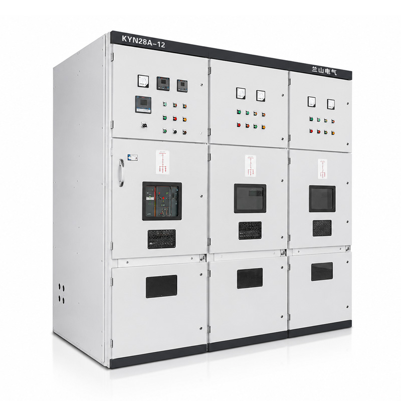
Then verify the interface with the downstream low voltage switchgear, cables and bus connections. The 738 A calculated in the factory example describes the assumed load; it does not independently select a circuit breaker or establish cable ampacity.
For expansion projects, state whether transformers will operate separately or in parallel. Do not assume two units are compatible because their nominal voltage ratios and kVA ratings match.
Choosing Between Dry-Type and Oil-Immersed Designs
The load calculation establishes the duty to be supplied; the construction choice also requires an installation review. For dry-type equipment within its scope, IEC 60076-11 is a relevant product standard. Loading assessments should use the appropriate guide for the selected construction.
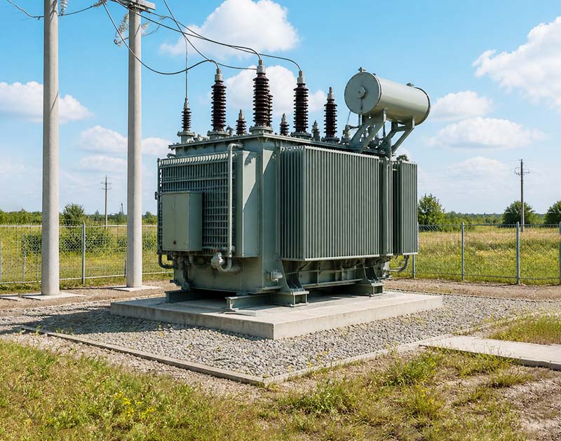
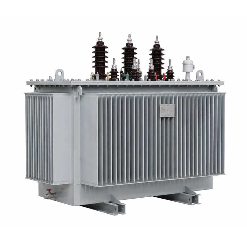
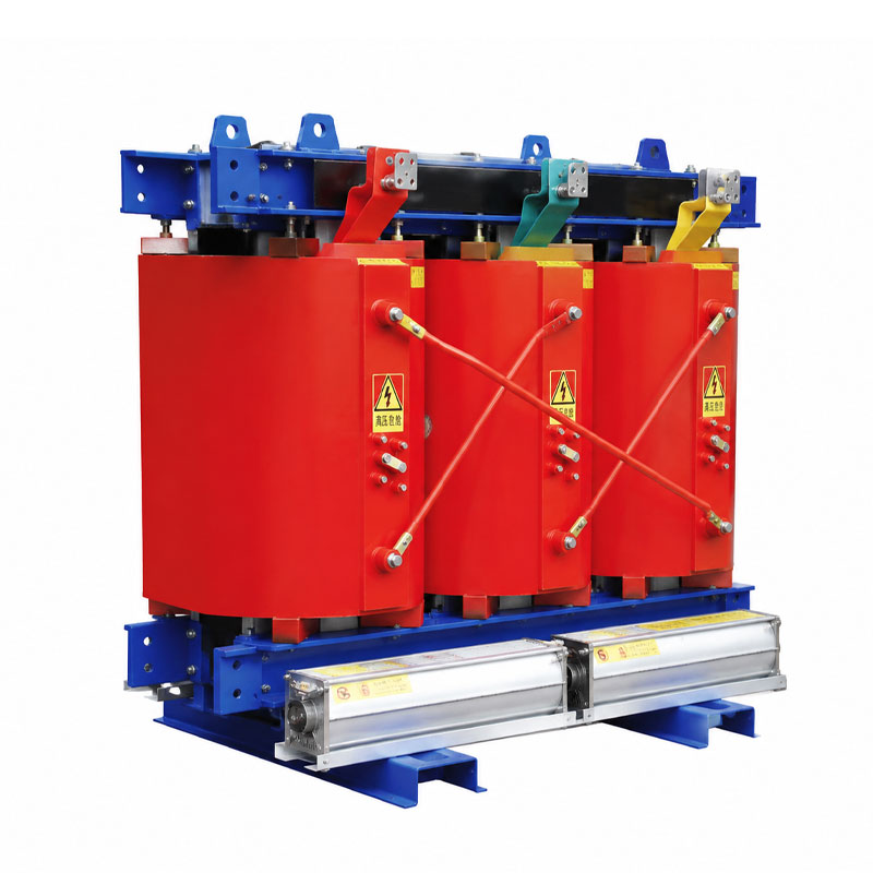
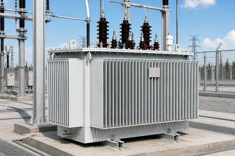
Lanshan’s transformer range includes a 10kV dry-type transformer and an oil-immersed transformer. These provide starting points for a configuration discussion, rather than substitutes for an approved project datasheet.
Keep the same distribution transformer sizing assumptions when comparing designs. Request confirmation of the cooling arrangement, applicable site conditions, physical clearances and required installation provisions. Otherwise, two proposals with the same headline capacity may be based on different duties.
What to Send with a Transformer Enquiry
A useful distribution transformer sizing enquiry includes the calculation and its supporting inputs, not just the requested kVA. Use the following as a procurement checklist rather than a universal compliance schedule.
| Project input | Information to provide | Confirmation to request |
|---|---|---|
| Electrical supply | Primary and secondary voltage, frequency, phases | Proposed voltage ratio and tapping arrangement |
| Operating demand | Load schedule, concurrent demand, power factor | Capacity basis and stated assumptions |
| Special loads | Motor-starting and harmonic information | Required studies or design provisions |
| Site conditions | Temperature, altitude, enclosure and ventilation | Applicable cooling rating and limitations |
| System interfaces | Single-line diagram, protection and grounding requirements | Impedance, vector group and connection details |
| Expansion | Identified additions and timing | Present and future operating scenarios |
Keep a revision date on the distribution transformer sizing schedule. When a load changes, update its demand contribution and flag the affected assumptions before asking suppliers to revise their proposals. This avoids comparing one offer based on the original process layout with another based on a later expansion.
Request an approved datasheet, dimensional drawing and agreed test-document schedule before final acceptance. Specify which technical questions remain open and who will approve each answer.
Lanshan’s power transformer range can be reviewed against these requirements. Keep model-specific guarantees separate from broad series descriptions.
Conclusion
Good distribution transformer sizing connects a credible operating scenario to a verified equipment configuration. Calculate simultaneous demand, use the corresponding power factor and distinguish planned growth from uncertainty. Then resolve starting, harmonic, thermal and system-interface requirements before approval.
To discuss a suitable configuration, contact Lanshan Electric with your load schedule, single-line diagram, voltage requirements and installation conditions. Include the expansion plan so the review can address both the initial installation and its next stage.
FAQ
What is the basic distribution transformer sizing formula?
Divide simultaneous electrical demand in kW by the corresponding aggregate power factor to obtain kVA. For example, 400 kW at 0.90 power factor equals approximately 444.4 kVA, before the remaining application checks.
Can I size a transformer from monthly electricity consumption?
Not from monthly kWh alone. Energy over a period does not identify the peak demand within it. Request interval demand data and the operating profile rather than treating average consumption as maximum load. The transformer efficiency guide also distinguishes average and peak loading.
Should distribution transformer sizing always include 25% spare capacity?
Use a documented project allowance rather than assuming one percentage suits every facility. Separate approved additions from uncertain growth and the preferred operating headroom. Do not count the same expansion twice or use spare capacity as a substitute for application studies.
Is a 630 kVA transformer enough for a 500 kW load?
At 0.90 power factor, 500 kW equals about 555.6 kVA; at 0.80, it equals 625 kVA. Neither calculation alone establishes suitability. Actual cooling conditions, load duration, starting duties and other project requirements still need review.
Does choosing a dry-type transformer change the kVA calculation?
The basic load conversion remains the same. What changes is the construction-specific assessment of cooling, operating conditions and loading capability. Compare the designs against identical load assumptions and obtain confirmation for the proposed installation.