Medium voltage switchgear selection should begin with a factory’s power routes, not a cabinet count. Which transformer supplies each production area? What must happen when one feeder trips? How will the next production line connect without forcing a redesign of the existing installation?
For plant owners and project engineers, those questions produce a better specification than a voltage and current rating alone. This guide follows the supply from the utility connection through the transformer feeders, with a worked expansion example and the decisions that need to be settled before manufacture.
What Medium Voltage Switchgear Does in a Factory
Medium voltage switchgear receives and distributes power through switching, protection, isolation and measurement functions. In a factory with local distribution transformers, its outgoing feeders connect the incoming supply to those transformers rather than directly to every low-voltage machine. Lanshan’s guide to how medium voltage switchgear works introduces those functions.
The design task is to decide where each function belongs. A utility incomer, transformer feeder and bus coupler can share a cabinet family while requiring different instruments, protection logic and operating conditions.
Create the functional single-line diagram first. Use it to determine the panel schedule, not the other way around.
Map Production Areas to Transformer Feeders
For medium voltage switchgear planning, divide the factory into meaningful electrical areas: production halls, utilities and independently developed buildings. Then identify which areas genuinely need separate transformer supplies.
Consider the following planning matrix. These are questions for an illustrative factory, not mandatory arrangements for every industrial project.
| Factory area | Feeder decision | Question that affects the design |
|---|---|---|
| Main production hall | Dedicated transformer feeder or shared supply | Must this area be isolated without disconnecting another hall? |
| Cooling and compressed air | Utility transformer or shared distribution | Which production areas depend on these common services? |
| Remote warehouse | Central supply or local transformer | What cable route and voltage performance are acceptable? |
| Future production building | Equipped spare feeder or later extension | How will the new circuit be connected and commissioned? |
Keep process dependence visible. Two production halls on different feeders may still stop together if both rely on one cooling system. Separate feeders address electrical boundaries, not every shared operational dependency.
Record the maximum acceptable interruption for each area and which services are needed for a controlled shutdown.
For widely separated buildings, compare extending the MV network to a local transformer with extending the existing low-voltage distribution. Assess cable routes, voltage performance and the new maintenance boundary together. A load-flow study evaluates steady-state power flow and voltages; distance alone should not decide the arrangement. This makes medium voltage switchgear planning part of the site layout, not simply an equipment-room exercise.
Confirm the Utility Interface Before Selecting the Incomer
The incoming medium voltage switchgear specification should identify the service voltage, frequency, earthing arrangement, available fault information and metering boundary. IEEE 3001.2 describes the exchange of utility-system and facility-load information needed to establish the electrical service interface.
Obtain the utility’s requirements for ownership, access, metering and protection approval. Distinguish a confirmed network value from a preliminary design assumption.
Do not treat nominal system voltage as the complete insulation specification. Have the designer establish the required equipment ratings and insulation levels. For an IEC-based metal-enclosed assembly within its scope, IEC 62271-200 is a relevant product standard; it is not a statement that every model covers its entire voltage range.
Choose the Supply Arrangement Around Defined Outages
Evaluate medium voltage switchgear against three separate events: loss of the incoming supply, a transformer-feeder fault and planned equipment maintenance. A configuration that helps with one may not solve the others.
Single Incoming Supply
A radial arrangement can be a reasonable candidate when the plant accepts the defined incoming-supply outage and individual transformer feeders provide sufficient operational separation. Establish that acceptance explicitly rather than calling the arrangement universally reliable or unreliable.
Sectionalized Bus with Alternative Supply
Where the operating objective calls for an alternative supply path, compare bus sections, incomers and a coupler against a written operating-mode schedule. Identify normal positions, permitted transfers and prohibited source combinations.
For medium voltage switchgear with transfer provisions, require load-flow and fault-duty checks for each permitted mode. These studies address different questions: voltage and loading performance versus fault-current and equipment duty.
Two incoming cables are not evidence of independent sources. Trace the upstream supply and specify the interruption the process can tolerate. A coupler is not an uninterrupted power supply.
Also distinguish a lost source from a failed transformer. An alternative MV source may resupply a healthy transformer, but it cannot make a failed transformer usable. Check whether the downstream arrangement provides another route to the affected loads. For medium voltage switchgear with an emergency supply mode, name the loads that remain connected and those that must be shed. Avoid approving an operating mode whose surviving equipment cannot carry its assigned demand.
Calculate Transformer Feeder Current on the Correct Side
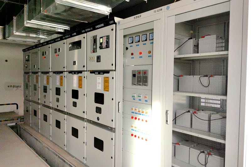
Use the voltage at the medium voltage switchgear connection when estimating primary feeder current. Do not copy the much larger low-voltage secondary current into the MV feeder schedule.
For a balanced three-phase planning calculation:
Current in amperes = apparent power in kVA ÷ (√3 × line-to-line voltage in kV)
Worked Example: A Factory Planning Another Production Hall
Assume a hypothetical 10 kV supply with two 1,000 kVA transformers and one 630 kVA transformer. A future hall adds another 1,250 kVA unit. Assume balanced loading at nominal apparent-power ratings and equal load power factors. Transformer losses and magnetizing current are omitted from this screening calculation.
| Feeder | Planning transformer capacity | Approximate primary current at 10 kV |
|---|---|---|
| Production hall A | 1,000 kVA | 57.7 A |
| Production hall B | 1,000 kVA | 57.7 A |
| Common utilities | 630 kVA | 36.4 A |
| Initial total | 2,630 kVA | 151.8 A |
| Future production hall | 1,250 kVA | 72.2 A |
| Expanded total | 3,880 kVA | 224.0 A |
These calculated values are not Lanshan product specifications, approved demand estimates or protection settings.
The example shows why medium voltage switchgear needs separate incomer and feeder schedules. It also shows why a relatively low running current cannot answer the fault-rating question. Confirm actual simultaneous demand through the load study, and determine protection settings separately from breaker continuous-current ratings.
Check Fault Duty for Every Permitted Source Configuration
For medium voltage switchgear, keep continuous current, short-time withstand current and duration, peak withstand, and circuit-breaker making and breaking duties distinct. IEC 62271-100 addresses AC circuit-breaker making and breaking tests; breaker capability must be considered alongside the assembly requirements.
Use the project fault study rather than selecting a kA value from another factory. IEC 60909-0 provides a calculation framework for short-circuit currents in three-phase AC systems. Agree the applicable edition and study assumptions.
Ask the study engineer to include permitted parallel sources, relevant motor contributions and credible future changes. Evaluate maximum duty and the conditions needed for protection to detect lower fault currents. Do not assume that an acceptable normal-open arrangement remains acceptable with its bus coupler closed.
Spare thermal capacity and spare fault-duty capability are separate acceptance questions.
Coordinate Transformer Protection with Downstream Circuits
A transformer feeder should have an agreed protection zone: identify the cable, transformer and associated interfaces it is intended to protect. Then define which device clears faults at each location and which device provides backup.
IEEE 3004.11 addresses bus and switchgear protection and isolation strategies. For medium voltage switchgear, use that system-level approach instead of evaluating the relay independently of the breaker and surrounding circuits.
Provide transformer impedance, connection details and relevant energization information. Ask the protection engineer to reconcile transformer inrush, downstream fault clearing and equipment withstand within the approved scheme.
Specify current-transformer requirements and the complete trip-power arrangement. Assign responsibility for calculating settings, approving them and verifying their implementation. Review the selected distribution transformers together with their feeders rather than finalizing each package in isolation.
Treat Large Motor Starting as a Separate Study
A running-load calculation does not establish acceptable voltage during motor acceleration. IEEE 3002.7 addresses motor-starting current, voltage drop and the system assumptions needed for that analysis.
For medium voltage switchgear serving a factory with large motors, submit the starting method, acceleration requirements, starting frequency and loads already operating. Include motors supplied through downstream transformers where relevant to the study.
Distinguish a feeder supplying a separate motor controller from an assembly that must perform the motor-starting duty itself. A general-purpose transformer-feeder specification is not a complete motor-control specification.
If startup performance is unacceptable, evaluate the supply and starting arrangement. A larger switchgear continuous-current rating alone does not resolve a calculated voltage dip.
Match Withdrawable Panels and RMUs to Their Actual Duties
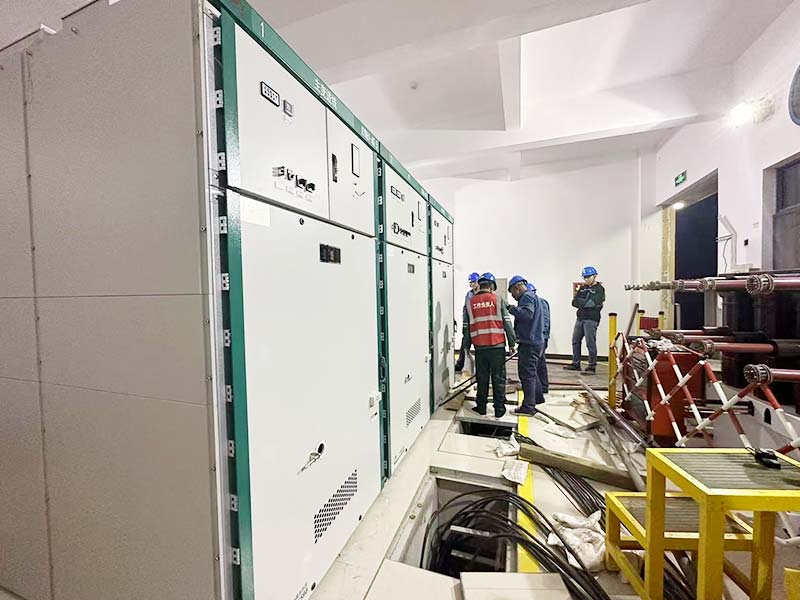
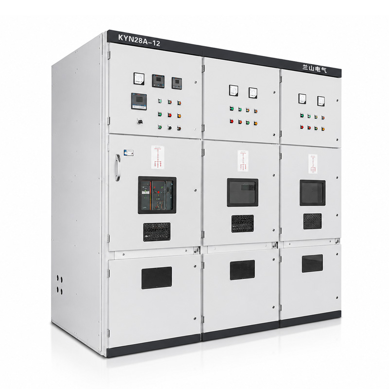
Lanshan’s KYN28A-12 medium voltage switchgear is described with a withdrawable vacuum circuit breaker and separate breaker, busbar, cable and low-voltage control compartments. Those features make it a candidate for a factory’s compartmentalized breaker lineup.
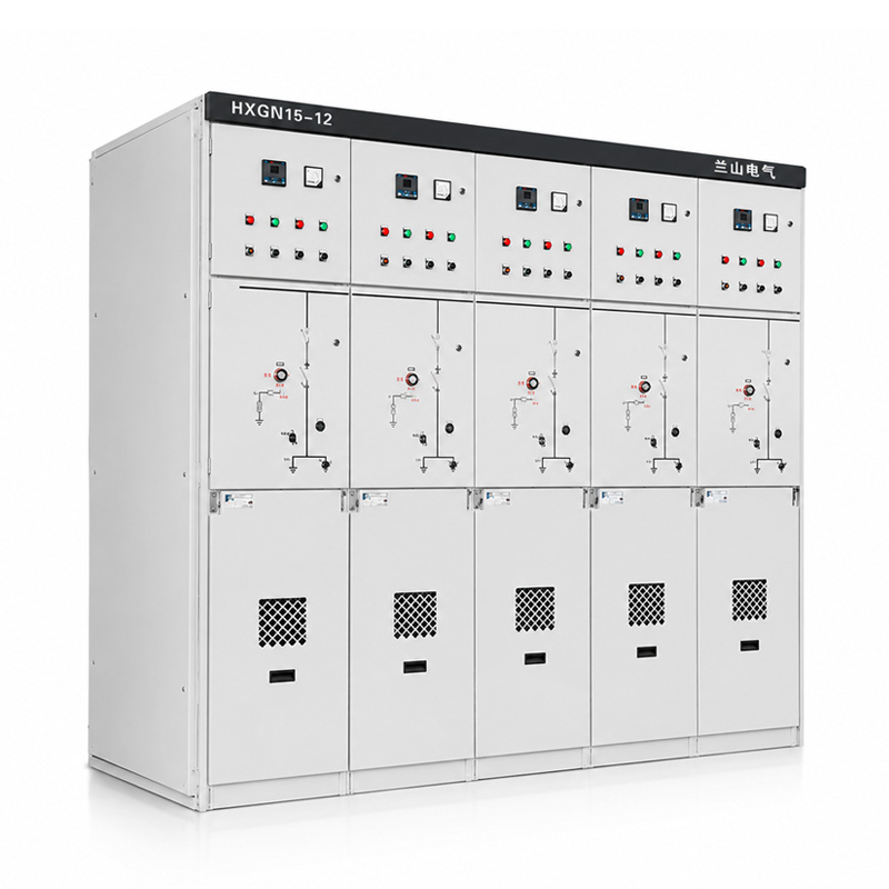
Its HXGN15-12 ring main unit describes configurable incoming, outgoing, transformer-protection and metering functions for secondary distribution. Evaluate it where those duties match the network arrangement.
Do not make the choice from footprint alone. A load-break switch must not be assumed to have a circuit breaker’s short-circuit interruption duty. Identify the actual protection arrangement in each offered feeder.
Request model-specific insulation, ratings and drawings. Neither product-family name establishes every configuration shown in a broad catalogue table.
Define Maintenance Access Without Assuming Live-Work Permission
For medium voltage switchgear, specify the actual maintenance task: breaker removal, cable-compartment access or busbar work. Require the supplier to show what must be isolated for each task.
Keep the declared loss of service continuity category, partition class and internal arc classification separate. Under IEC 62271-200, these describe different characteristics; one designation does not establish all three. Request the applicable declarations and supporting evidence for the offered arrangement.
Withdrawable construction is not permission for energized maintenance. Switching and access require authorized personnel, the manufacturer’s instructions and applicable safe-working procedures. IEC 61936-1 distinguishes installation design from subsequent maintenance and repair activities.
Coordinate the Switchroom, Cable Trench and Environment
Review medium voltage switchgear on a complete room drawing. Show the breaker-handling route, access doors, cable trench, installation clearances and any required arc-pressure exhaust route.
Provide actual cable sizes, quantities, termination types and entry directions. Ask the supplier to confirm termination space and support details before the foundation and trench drawings are frozen.
Include ambient temperature, altitude, humidity and contamination. A factory room near dusty processing equipment needs an exposure review, not just an indoor designation. Electrical-installation requirements and the product’s declared service conditions must be considered together.
Keep incoming metering access and maintenance access clear after other building services are installed. Confirm delivery masses and transport sections, including how a replacement breaker reaches its service area.
Plan Expansion as a Connection Project, Not an Empty Space
For medium voltage switchgear expansion, distinguish an equipped spare feeder, an unequipped panel position and an extensible end of the lineup. Ask exactly what is included and how the future circuit will connect.
Return to the worked example. The future transformer raises the simplified incomer current from 151.8 A to 224.0 A. Even if the proposed bus supports that duty, the project still needs a feeder, cable route, protection channel and commissioning plan.
Reserve the physical extension direction and obtain the manufacturer’s interface requirements. Establish the shutdown needed for adding panels; do not promise uninterrupted expansion without an approved procedure.
A changed arrangement also needs evidence review. IEC TR 62271-307 addresses extension of type-test validity for relevant equipment, rather than treating every related design as automatically covered.
Make Acceptance Tests Follow the Operating-Mode Schedule
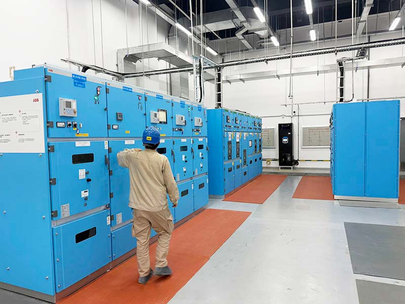
Before manufacture, agree how the medium voltage switchgear will demonstrate the specified control functions. Include permitted and blocked commands, breaker status, trip indications and responses to loss of auxiliary power.
Where transfer is supplied, identify the simulated inputs and expected result for each approved mode. Record who checks the external utility, generator or plant-control interfaces at site.
For medium voltage switchgear with a separately powered trip circuit, follow the test scope from the relay output through the supplied wiring to the breaker. Identify any battery, charger or external supply excluded from the factory setup. Record how the complete tripping arrangement will be checked after installation; a working monitoring display is not proof that the trip path has been verified.
Keep design evidence, routine production tests and functional acceptance distinct. A successful opening command does not prove the assembly’s fault withstand. IEC 62271-200 provides the relevant assembly framework; the project test plan must identify what each acceptance activity establishes.
Prepare a Project-Specific Enquiry for Lanshan
Send the single-line diagram, transformer and feeder schedules, utility data and switchroom layout together. Add the permitted supply modes, expansion plan, cable details and required verification documents.
Use Lanshan’s medium voltage distribution equipment range to begin the configuration discussion. For KYN28A-12, request the exact rated voltage, current, fault-duty duration, insulation and access classifications rather than applying series limits to the proposed unit.
Ask for an approved rated-data schedule and a list of technical deviations. Keep uncertain utility inputs visible until the responsible engineer confirms them.
Conclusion
Select medium voltage switchgear by connecting the factory’s supply arrangement to its transformer feeders, protection requirements and next expansion. Running current is only one input; fault duty, maintenance boundaries and installation interfaces need their own checks.
Contact Lanshan Electric with your single-line diagram, system voltage and fault-level data to discuss a configuration matched to your factory’s operating plan.
FAQ
How do I select medium voltage switchgear for a factory?
Start with the utility interface, transformer-feeder schedule and permitted operating modes. Confirm load current, fault duties, protection, maintenance access and installation conditions before approving a particular cabinet configuration.
Does every production machine need a medium-voltage feeder?
No. In the arrangement described here, MV feeders supply local transformers, while low-voltage distribution supplies individual machines. Direct MV motor supplies need their own defined control and protection arrangement.
Can I choose switchgear from transformer kVA alone?
No. Transformer kVA supports a running-current estimate, but it does not establish utility fault current, breaker interruption duty, protection settings or installation suitability. Short-circuit analysis requires a model of the relevant supply system.
Does a bus coupler guarantee continuous production?
No. Review source independence, transfer interruption, surviving capacity and common process utilities. An alternative electrical path is useful only when the approved operating arrangement supports the required loads.
What should I reserve for future medium voltage switchgear expansion?
Reserve the required feeder provision, physical space, cable routes and control interfaces. Also define the permitted shutdown, future source conditions and review of ratings and verification evidence before the expansion is approved.