A capacitor bank panel should match the way reactive power changes in the actual electrical system. A fixed bank can be effective when the inductive load is stable, while an automatic APFC panel can add or remove capacitor stages as demand changes. Choosing between them is therefore a control problem as much as a kvar calculation.
For factories, commercial buildings and utility auxiliaries, the wrong compensation method can create leading power factor, unnecessary switching, capacitor stress or interaction with harmonic-producing loads. This guide compares fixed and automatic approaches through the operating conditions that project engineers and buyers need to verify before specifying equipment.
What Does a Capacitor Bank Panel Actually Do?
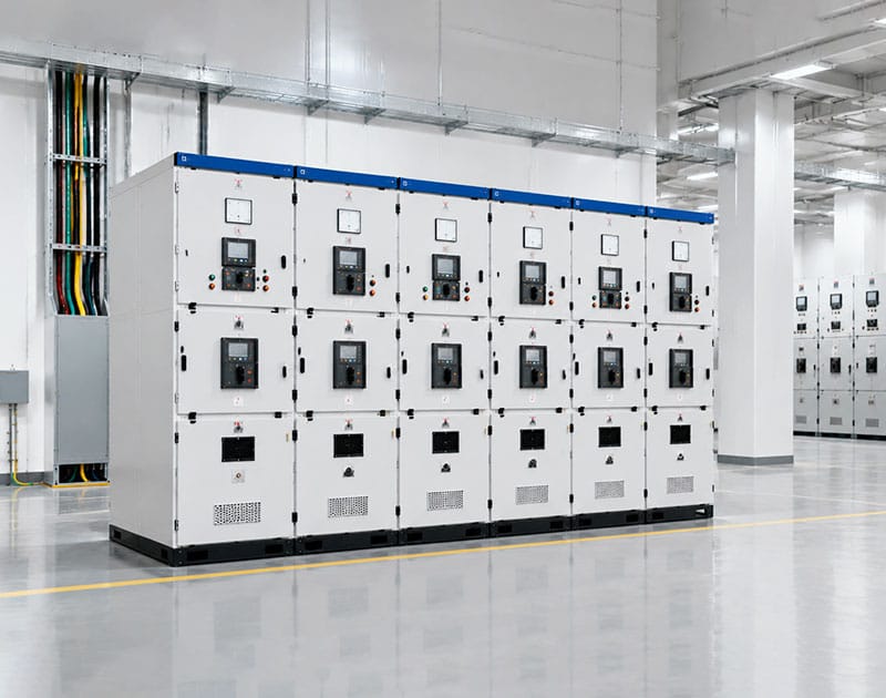
A capacitor bank panel supplies capacitive reactive power locally so that part of the inductive reactive demand does not have to travel through upstream cables and transformers. The U.S. Department of Energy explains the relationship between real power, reactive power and apparent power in its voltage and reactive power guidance. Lower reactive current can reduce current carried by parts of the distribution system when the correction is appropriately applied.
For low-voltage correction, IEC 61921:2017 applies to low-voltage AC shunt capacitor banks used for power-factor correction, including banks equipped with switchgear and controlgear that connect or disconnect parts of the bank. Individual self-healing capacitor units and banks are addressed by IEC 60831-1:2014 within its scope.
Those standards do not tell a project which correction method to choose. That decision starts with the load profile, required target power factor, harmonic environment and control philosophy.
Fixed vs Automatic Compensation at a Glance
| Decision point | Fixed capacitor bank | Automatic APFC panel | What the buyer should verify |
|---|---|---|---|
| Reactive output | Constant kvar while connected | Changes by switching stages | Load variation and required step resolution |
| Best fit | Stable or separately switched inductive load | Bus with changing combinations of loads | Measured kvar profile over representative periods |
| Control | Simple switching arrangement | Controller plus contactors or other approved switching devices | Target PF, switching logic and response behavior |
| Over-correction risk | Higher when the compensated load falls away | Reduced when stages are removed correctly | Minimum load and leading-PF limits |
| Switching duty | Low if the operating pattern is stable | Potentially frequent | Expected operations, stage size and switching device duty |
| Harmonic review | Required where nonlinear loads are significant | Also required; automatic control does not remove harmonics | THD spectrum, system impedance and resonance assessment |
The table shows why a capacitor bank panel cannot be selected from kvar alone. The same total capacitor capacity can behave very differently depending on how it is divided into steps and when those steps are connected.
When a Fixed Capacitor Bank Makes Sense
A fixed capacitor bank panel is worth considering where reactive demand is predictable and closely tied to a stable inductive load. The clearest example is a motor or transformer duty that remains substantially unchanged whenever the capacitor is energized.
The engineering question is whether the capacitor bank panel can remain matched to that load throughout its operating cycle. If the machine is stopped while the capacitor remains connected to the bus, the system can move toward a leading power factor. That possibility should be addressed in the switching arrangement and operating logic rather than left to an operator to notice later.
Fixed compensation can also reduce control complexity. There is no multi-step controller continuously adding and removing kvar. However, simplicity only helps when the electrical duty is genuinely simple. A bank connected to a fluctuating common bus can become the wrong amount of compensation for much of the day.
Do Not Use “Fixed” as a Synonym for “Always Energized”
A fixed capacitor bank panel can still be switched with the load it is intended to compensate. In project documents, define the interlocking or switching condition explicitly. The important distinction is that its reactive output is not automatically modulated through multiple steps in response to a changing bus power factor.
When an Automatic APFC Panel Is the Better Fit
An automatic capacitor bank panel is designed for buses where the required reactive compensation changes as loads start and stop. An APFC controller monitors an electrical quantity, evaluates the reactive-power requirement and commands stages to connect or disconnect according to the configured logic.
This automatic capacitor bank panel approach suits manufacturing plants with changing production lines, commercial buildings with cycling HVAC loads and other installations where one fixed kvar value would frequently be too much or too little. The objective is not to chase every small fluctuation; it is to keep the system within an agreed operating range without excessive switching.
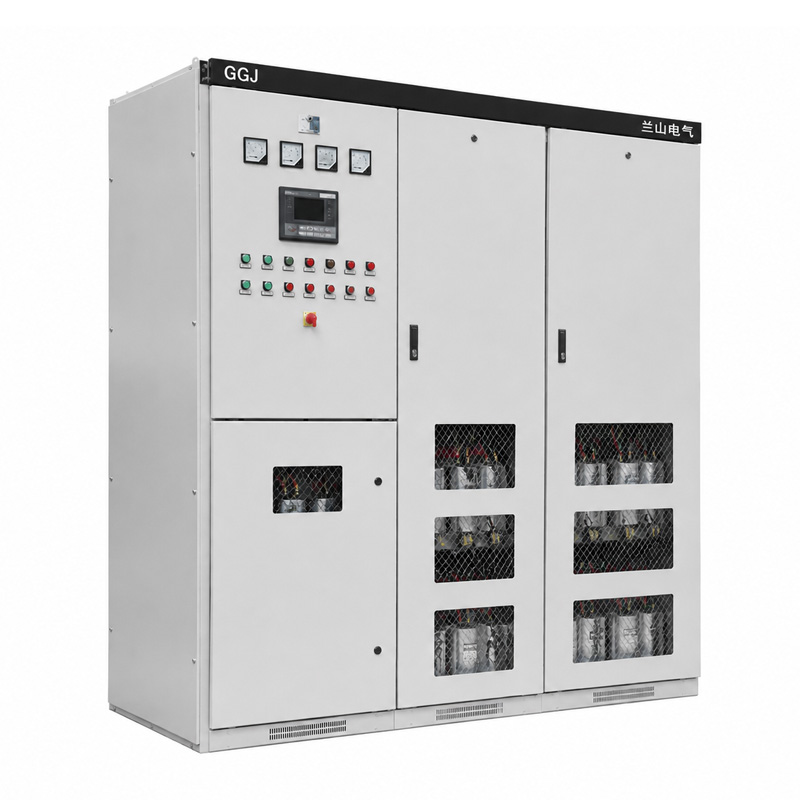
Lanshan’s GGJ automatic low-voltage reactive power compensation cabinet is the relevant product direction for an automatically controlled capacitor bank panel. Project-specific step sizes, switching devices, controller functions and applicable ratings still need to be confirmed from the approved proposal rather than inferred from the product-family name.
Size the Bank from Reactive Power, Not from Guesswork

For a load with real power P, initial power factor cosφ1 and target power factor cosφ2, a common planning relationship is:
Required capacitor kvar ≈ P × (tanφ1 − tanφ2)
This is a starting calculation, not a final panel specification. For a capacitor bank panel, the load used in the formula must correspond to a realistic operating condition, and the target power factor should follow project or utility requirements rather than an arbitrary value close to unity.
Illustrative Calculation
Assume a facility draws 800 kW at 0.78 power factor and the engineering target is 0.95. The phase-angle tangents are approximately 0.802 and 0.329, so the calculated compensation is about 378 kvar.
That result does not mean the buyer should automatically order a 400 kvar fixed bank. If the facility regularly drops to half load, the reactive requirement will change. The next step is to compare the kvar requirement across representative operating periods and choose a control strategy and step structure that can follow those changes.
Step Size Matters as Much as Total kvar
For an automatic capacitor bank panel, total capacity answers only one question. Step size determines how closely the system can follow changing reactive demand. Very large steps can cause the corrected power factor to move back and forth across the target; very small steps increase the number of switching operations and may add unnecessary complexity.
Consider an illustrative 300 kvar bank. A 6 × 50 kvar arrangement and a 25 + 25 + 50 + 50 + 50 + 100 kvar arrangement have the same total kvar but different resolution and operating sequences. Neither is universally superior. The correct structure depends on the measured load profile, controller algorithm and switching-duty limits.
Ask the supplier to show the proposed stage sequence and the resulting available kvar combinations. Also define how the controller avoids rapid reconnection after a stage is disconnected, because capacitors require the specified discharge conditions before re-energization.
Avoid Leading Power Factor and Light-Load Over-Correction
A capacitor bank panel that supplies more capacitive kvar than the system needs can drive the power factor leading. This risk is especially relevant at night, during weekend operation or when only a few production lines remain energized.
Do not review only the plant’s peak load. Include its minimum credible operating condition. If a fixed bank remains connected during that minimum, calculate the resulting reactive balance. For an APFC arrangement, confirm that the smallest connected step can be removed and that the controller has an appropriate response to leading conditions.
Transformer magnetizing reactive demand and other background loads may remain when production equipment is off, but they should be measured or calculated rather than assumed to justify a permanently connected bank.
Harmonics Can Change the Correct Compensation Design
A standard capacitor bank panel provides reactive compensation; it does not automatically correct waveform distortion created by nonlinear loads. Drives, rectifiers and other power-electronic equipment can inject harmonic currents that require a separate power-quality assessment.
Published IEEE research on capacitor applications describes how power-factor capacitors can interact with system inductance and create resonance near harmonic frequencies. That interaction can amplify harmonic current or voltage and contribute to overheating, nuisance operation or capacitor stress when the system is not properly assessed.
Therefore, provide harmonic spectra or representative THD measurements where nonlinear loads are significant. Ask the engineer whether a conventional bank is suitable, whether detuning reactors are required, or whether a different harmonic-mitigation solution is needed.
Do Not Confuse Reactive Compensation with Harmonic Filtering
A detuned or tuned arrangement adds reactor characteristics that change the electrical behavior of the capacitor bank panel. It should be specified from a harmonic study, not added because the word ‘drive’ appears on the load schedule. Equally, an automatic APFC controller does not make a conventional capacitor bank an active harmonic filter.
Switching Devices Need to Match Capacitor Duty
Capacitor switching is different from switching a resistive load. Energization can involve high transient current, and repeated operations place duty on contactors or other switching devices. The selected components should be suitable for the capacitor stages and their intended operating frequency.
For a capacitor bank panel, request the switching-device type, ratings, expected operating sequence and any required inrush-limiting arrangement. The supplier should also identify protection for each stage and the complete assembly’s short-circuit characteristics.
IEC 61921:2017 specifically addresses low-voltage power-factor correction banks and aligns applicable assembly requirements with IEC 61439-1 and IEC 61439-2. The individual capacitor characteristics remain subject to the applicable capacitor standards.
Thermal Design and Ventilation Still Matter
A capacitor bank panel contains components that dissipate heat: capacitor losses, switching-device losses, controller power and any reactors included in the design. The enclosure must therefore be assessed as a complete thermal system under the proposed ambient conditions.
Provide the switchroom temperature, altitude, ventilation constraints and any nearby heat sources. Where reactors are used, their contribution to enclosure temperature can be significant and should be included in the design review.
Do not assume that opening additional ventilation slots is an acceptable field fix. Enclosure changes can affect ingress protection, temperature-rise verification and the arrangement covered by the supplier’s evidence.
Measure the Correct Current Transformer Signal
An automatic capacitor bank panel depends on correct sensing. If the current transformer is installed at the wrong point, has the wrong polarity or does not represent the intended bus, the controller can make incorrect switching decisions even when the capacitor stages themselves are healthy.
Define the CT location on the single-line diagram and identify which loads and capacitor currents are included in the measurement. Confirm ratio, polarity, secondary rating and connection to the controller.
For a system with multiple incomers or a bus coupler, explain each permitted operating mode. A sensing arrangement that works with one incomer may not correctly represent power flow after the bus configuration changes.
Example: Why One Factory Needs Automatic Staging
Consider a hypothetical factory with three production lines. During the morning, all three lines operate and the calculated compensation requirement is about 360 kvar. At lunch, one line stops and the requirement falls to approximately 240 kvar. During an evening cleaning shift, only utility loads remain and the requirement falls below 100 kvar.
A 350 kvar fixed capacitor bank panel could be close to the daytime requirement but excessive during the evening condition. An automatic bank with an appropriately selected stage structure can reduce connected kvar as the inductive demand falls.
This example does not establish a universal stage schedule. It shows why the buyer should provide a time-based load profile rather than only the maximum kW value. The final design must also account for harmonics, target power factor, switching duty and utility requirements.
What Buyers Should Put in the RFQ
| RFQ input | Why it matters | Supplier response to request |
|---|---|---|
| System voltage and frequency | Defines capacitor and switching duty | Rated voltage, frequency and applicable tolerance |
| Load profile by operating period | Shows how reactive demand changes | Recommended fixed or staged compensation strategy |
| Existing and target power factor | Defines correction objective | Calculated kvar basis and control target |
| Harmonic measurements or load types | Identifies resonance and distortion concerns | Need for reactor or additional power-quality study |
| Fault level and upstream protection | Affects assembly protection and withstand | Protection scheme and short-circuit characteristics |
| Ambient and installation conditions | Affects temperature and enclosure design | Cooling, derating and enclosure requirements |
| Monitoring and communications | Defines integration scope | Metering, alarms, controller signals and interface |
For a GGJ-based capacitor bank panel enquiry, send the single-line diagram, transformer rating, measured load data and major nonlinear loads together. This gives Lanshan a technical basis for proposing total kvar, stage sizes and control functions.
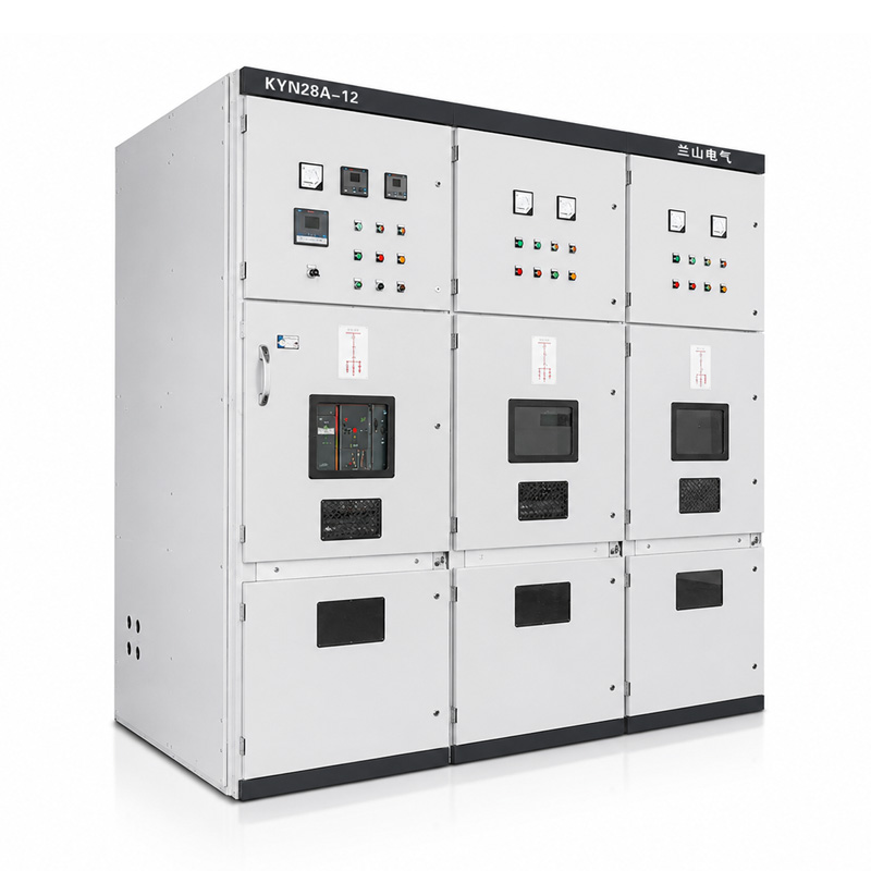
If the project also includes main distribution equipment, coordinate the capacitor bank panel with Lanshan’s low-voltage switchgear range. The compensation cabinet and the main switchboard should use consistent fault-level, cable and operating-mode assumptions.
How to Compare Fixed and Automatic Proposals
Compare each capacitor bank panel offer on the same operating cases. Do not choose an automatic panel merely because it has more components, and do not choose a fixed bank merely because it appears simpler. The correct capacitor bank panel solution is the one whose control behavior matches the load.
For each capacitor bank panel proposal, review total kvar, smallest step, stage sequence, controller target, switching device type, capacitor voltage rating, discharge arrangement, protection and thermal design. Where reactors are proposed, record their purpose and design basis.
Then ask what happens under minimum load, loss of the CT signal, loss of controller power and a failed stage. These operating questions expose important differences that a one-line capacity comparison will miss.
Conclusion
The choice between fixed compensation and an automatic capacitor bank panel depends on how reactive power changes over time. Stable loads may support a simple fixed approach; variable buses usually need staged control that can remove kvar as well as add it.
Before ordering, verify the load profile, target power factor, harmonic environment, step structure and sensing arrangement. Contact Lanshan Electric with your single-line diagram, transformer data and measured load information to discuss a GGJ reactive-power compensation configuration for your project.
FAQ
What is the main difference between a fixed capacitor bank and an APFC panel?
A fixed bank supplies a defined kvar whenever it is connected. An APFC panel switches capacitor stages according to the measured reactive-power or power-factor condition, making it better suited to buses with changing loads.
Can a capacitor bank panel correct harmonics?
A conventional capacitor bank panel corrects reactive power but is not automatically a harmonic filter. In systems with significant nonlinear loads, perform a harmonic and resonance assessment before deciding whether reactors or another mitigation method are required.
How do I calculate the required capacitor kvar?
A common planning formula is Qc = P × (tanφ1 − tanφ2), using the real power and the initial and target power-factor angles. The final bank size and stages should be checked against multiple operating conditions rather than one peak-load value.
Can an oversized capacitor bank cause problems?
Yes. Excess capacitive kvar can produce leading power factor, voltage changes and unnecessary capacitor stress. Review the minimum-load condition and ensure an automatic panel can disconnect enough stages when reactive demand falls.
What information should I send for a GGJ compensation cabinet enquiry?
Provide system voltage, transformer size, single-line diagram, load profile, existing and target power factor, harmonic information, fault data and installation conditions. Include any monitoring or communications requirements so the proposed configuration can be reviewed as a complete system.