A solar transformer can run hottest when a photovoltaic plant is producing near its maximum output, but a high temperature alarm does not automatically prove that the transformer is undersized. Peak generation can coincide with high ambient temperature, reduced cooling margin, reactive-power duty, harmonic losses or a local connection problem.
The useful question is not simply whether the plant reached 100% power. It is whether the solar transformer was operating within the thermal conditions and waveform assumptions used for its design. This guide shows EPC engineers and plant operators how to separate those possibilities before changing ratings, cooling settings or protection limits.
Why Peak Solar Generation Can Stress a Transformer
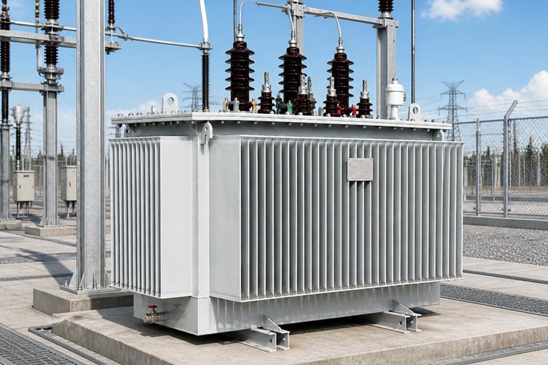
A photovoltaic plant usually drives power from the inverter side toward the medium-voltage collection network. As irradiance rises, inverter AC output increases and the solar transformer carries more current. Winding losses rise with current, while core loss remains present whenever the unit is energized.
At the same time, high solar output may occur during warm weather. The transformer therefore has to reject internally generated heat into an environment that may already offer less cooling margin. For mineral-oil units, IEC 60076-7 links loading, ambient temperature, operating temperature and thermal ageing. For dry-type units, IEC 60076-12 provides the corresponding loading framework.
The result is a thermal problem with several variables. A solar transformer that operates acceptably at the same electrical output on a cool morning may approach a different temperature during a hot afternoon. This is why load percentage alone is an incomplete diagnosis.
First Confirm That the Temperature Is Actually Abnormal
Before treating a reading as overheating, identify what is being measured. Top-oil temperature, winding hot-spot indication, enclosure-air temperature and an infrared surface reading are different quantities. Compare each value with the limit, alarm setting and sensor location defined for that measurement.
Review timestamps as well. Transformer temperature often lags changes in solar output because the active parts and insulating medium have thermal mass. The highest temperature may occur after the highest instantaneous generation. A chart that compares a noon power value with a later temperature alarm can therefore be meaningful, but only if the data are time aligned.
Check whether the monitoring channel is configured correctly. A changed sensor scaling, failed probe or incorrect tag can create an apparent thermal event. Independent verification by qualified personnel should be part of the investigation before the plant is derated or the solar transformer specification is changed.
Compare Active Power, Reactive Power and Apparent Power
Transformer current follows apparent power, not active power alone. For a three-phase system, apparent power is related to active and reactive power by S = √(P² + Q²). If the plant is exporting reactive power at the same time as real power, the transformer can carry more kVA than a MW-only dashboard suggests.
For example, consider a hypothetical plant exporting 2.4 MW and 0.8 MVAr during a grid-support period. The apparent power is approximately 2.53 MVA. The example is not a Lanshan rating or a recommendation; it simply shows why MW and MVA should not be treated as identical.
Include inverter power-factor or reactive-power commands in the solar transformer review. Also check whether the plant performs nighttime voltage support or other reactive operation when active generation is low. Depending on the project controls, the transformer may still carry current outside the normal generation profile.
Check Whether the Inverter Output Matches the Transformer Design Basis
A solar transformer should be reviewed against the number of inverters connected, their AC ratings, voltage, maximum operating current and control modes. The DC array size is useful project information, but it does not directly define transformer AC loading because the inverter limits and grid-export controls sit between the array and transformer.
Ask for the actual inverter operating data during the thermal event. If several inverters share one transformer, compare their outputs and determine whether one group was operating differently. Confirm whether any inverter replacement, firmware update or plant-control change altered the current or reactive-power profile.
Lanshan describes its solar transformer as a configurable renewable-energy transformer for utility-scale, distributed and industrial photovoltaic projects, with capacity, voltage ratio, cooling and protection selected to project requirements. Treat those options as a starting point for a project-specific datasheet, not as one universal thermal rating.
Do Not Ignore Harmonic Current and High-Frequency Components
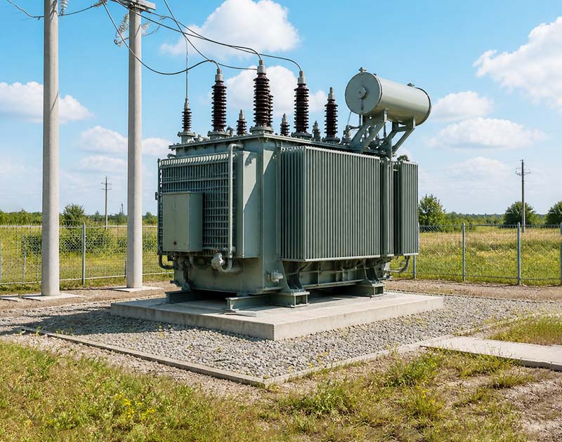
PV inverters use power electronics, so the current waveform is not perfectly sinusoidal. Modern inverters are designed to control distortion, but the correct engineering question is the harmonic spectrum that reaches the transformer under the plant’s actual operating conditions.
IEEE C57.110 provides methods for evaluating liquid-immersed and dry-type transformer capability when supplying nonsinusoidal load currents. Harmonic currents can increase eddy-current and other stray losses, which can raise winding temperature beyond what a simple fundamental-frequency current calculation predicts.
Do not apply a generic K-factor or automatic derating percentage to every solar transformer. Obtain the inverter manufacturer’s harmonic-current data at relevant output levels, and ask the transformer designer to confirm the loss and temperature-rise basis for that spectrum. If field measurements are used, record where they were taken and under which plant output condition.
Separate Harmonic Heating from High-Frequency EMC Issues
Low-order harmonic loading and higher-frequency switching components are related to power-electronic operation, but they are not the same engineering question. IEC 62920 sets EMC requirements for photovoltaic power-conversion equipment and recognizes equipment connected to medium- or high-voltage networks through transformers.
For a solar transformer overheating investigation, use measured or specified current-spectrum data rather than assuming that an EMC-compliant inverter eliminates every transformer loss concern. Conversely, a high-frequency waveform observed at one point in the system does not by itself prove that it caused the thermal alarm.
The practical approach is to correlate waveform data with current, temperature and operating state. That evidence is more useful than labeling the transformer simply as “harmonic loaded.”
Review Ambient Temperature, Solar Radiation and Enclosure Conditions
Outdoor renewable-energy equipment is exposed to more than the weather-station temperature. The local air around a solar transformer can be affected by direct sun, nearby inverter heat, reflected radiation, restricted airflow and the layout of a prefabricated enclosure.
Record ambient temperature close to the transformer, preferably in a location representative of its cooling air rather than a distant site sensor. Compare sunny and cloudy days with similar electrical output when possible. This helps separate generation-related heating from environmental heating.
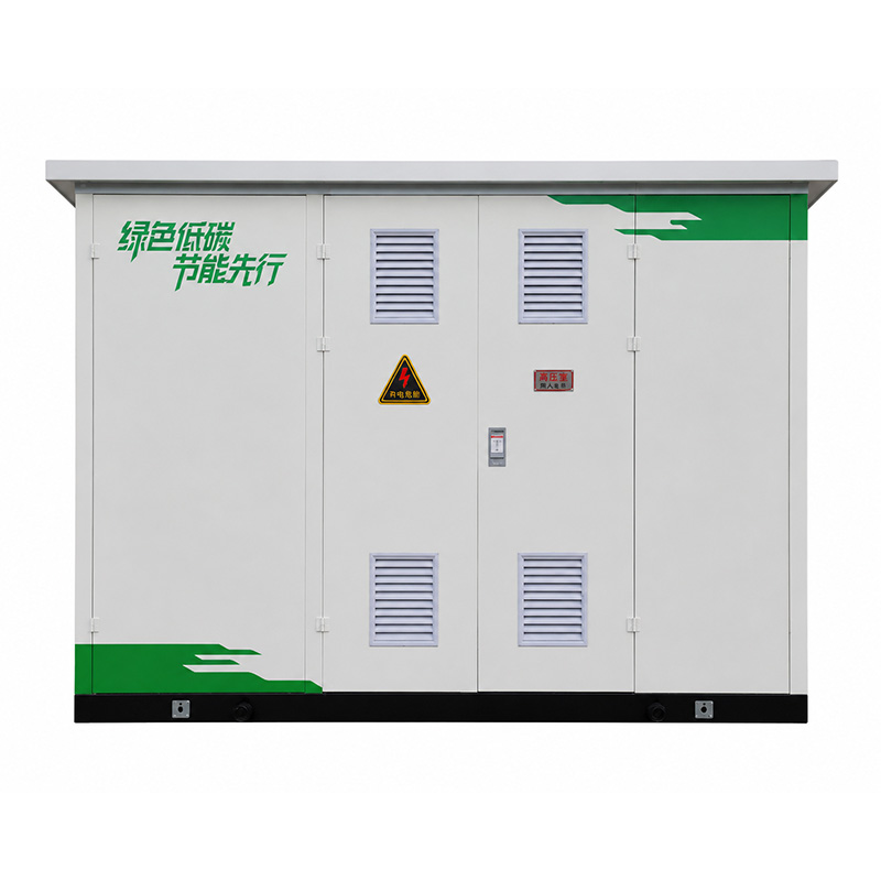
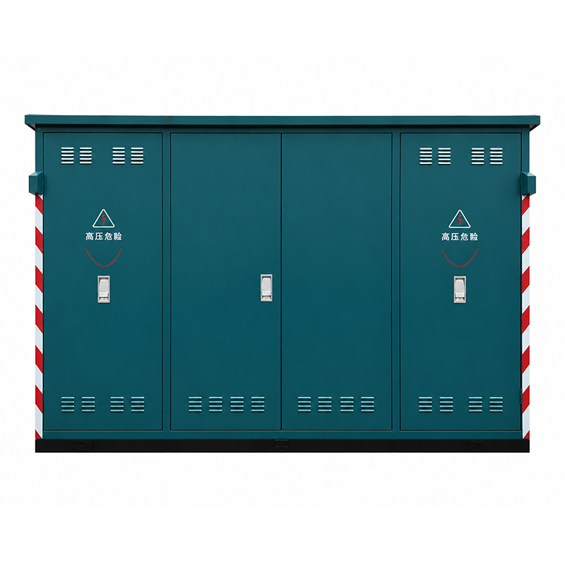
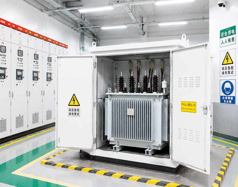
If the solar transformer is installed inside a compact substation, review the transformer and enclosure as one thermal system. Lanshan’s solar-transformer page lists oil-immersed and dry-type options and ONAN, ONAF, AN and AF cooling configurations. The permitted rating must be confirmed for the exact enclosure, cooling arrangement and site conditions.
Check Cooling Availability Before Blaming Transformer Capacity
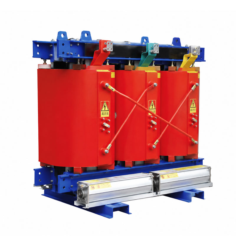
For an oil-immersed solar transformer, verify that the specified radiators, fans and other cooling provisions are available in the operating mode being reviewed. For a dry-type design, verify natural or forced-air cooling and the surrounding ventilation path.
A fan-start command is not proof of delivered airflow. Review fan status, auxiliary power, blocked radiators or filters, damaged louvers and any site change that could cause hot exhaust air to recirculate. The manufacturer’s maintenance instructions and approved safety procedures should govern inspection.
Keep normal and backup cooling ratings separate. If the plant depends on forced cooling to export full power, the operating procedure should state what happens when that cooling is unavailable. Increasing a temperature trip setting is not a substitute for resolving a cooling problem.
Look for Local Hotspots That a Plant-Level Load Percentage Can Hide
An enclosure-wide temperature rise points toward a different problem from one unusually hot terminal or connection. Localized heating can result from higher resistance, unequal current distribution or a connection condition even when the total solar transformer loading appears normal.
Compare phase currents and similar connection points. Qualified personnel can use appropriately corrected thermographic observations as one source of evidence, but the hottest color on an image is not a complete diagnosis. Surface condition, emissivity, viewing angle and load at the time of inspection affect interpretation.
A local hotspot should be investigated as an electrical connection issue rather than masked by adding more enclosure ventilation. Any internal inspection or corrective work must follow approved isolation procedures and the manufacturer’s instructions.
Use Daily Thermal Cycling as Part of the Design Review
Solar generation commonly rises after sunrise, reaches a daytime high and falls toward evening. That repeated loading cycle differs from a factory transformer that may operate at a relatively steady load for long shifts. The transformer design and loading review should reflect the actual duty rather than an assumed constant 100% load.
Thermal cycling does not automatically mean that a solar transformer needs a larger nameplate rating. Its significance depends on peak duration, ambient conditions, loss distribution, insulation system and cooling. Loading guides are intended to evaluate operating temperature and ageing over time, not to replace the manufacturer’s design data.
For a project with seasonal clipping or grid curtailment, include those operating modes as well. A transformer selected only from PV module DC capacity can be misleading because the AC export profile may be governed by inverter and grid limits.
Example: High Temperature During a Clear Afternoon
Consider a hypothetical solar plant where the transformer alarm appears on clear afternoons. The plant exports close to its permitted AC limit, and the alarm occurs about an hour after the generation peak. The transformer is not continuously above its nameplate kVA.
The investigation should first align inverter MW, MVAr, phase current, local ambient temperature, transformer temperatures and cooling status on the same timeline. Suppose the review finds that apparent power remains near the expected duty, but one cooling fan does not start and the local inlet air is significantly warmer than the site weather station reports.
Those observations would make cooling availability and local environment priorities for investigation. They would not yet prove that the transformer is correctly sized, nor would they rule out harmonic or connection issues.
Now suppose a second event occurs with all fans available, but current-spectrum measurements show an operating condition not included in the original transformer data. The engineering question changes. The next step is to have the transformer designer evaluate the measured spectrum and losses, not to assume the same root cause as the first event.
Build a Diagnostic Dataset Before Changing the Equipment
A useful solar transformer investigation should combine electrical, thermal and environmental evidence. The table below provides a practical data request for EPC teams and plant operators.
| Data group | What to collect | Why it matters |
|---|---|---|
| Generation and inverter data | MW, MVAr, kVA or current, inverter status and curtailment | Shows the actual electrical duty during the event |
| Transformer temperature | Top-oil, winding indication or dry-type sensors with timestamps | Identifies which thermal quantity is approaching its limit |
| Environment | Local ambient temperature, sun exposure and enclosure conditions | Separates electrical heating from reduced cooling margin |
| Cooling system | Fan or pump status, auxiliary supply and alarms | Confirms whether the intended cooling mode was available |
| Power quality | Current THD and harmonic spectrum where relevant | Supports evaluation of nonsinusoidal-current losses |
| Maintenance evidence | Thermography, connection history and recent modifications | Helps locate local rather than whole-transformer problems |
Know When a Larger Solar Transformer Is Actually Justified
A larger solar transformer may be justified when the approved future operating duty, after considering reactive power and waveform effects, exceeds the confirmed capability of the existing design. It can also be part of a redesign when the plant export limit or inverter capacity is intentionally increased.
It is not automatically justified because one temperature alarm occurred. If the root cause is unavailable cooling, a local high-resistance connection or an installation problem, increasing kVA may leave the fault in place.
Before changing capacity, ask the transformer manufacturer for the project-specific loading and thermal basis. For mineral-oil equipment, IEC 60076-7 provides guidance on temperature and loading; for dry-type equipment, IEC 60076-12 applies within its scope. The final decision should use the actual configuration, ambient conditions and expected duty.
What to Send Lanshan for a Solar Transformer Review
When requesting a new unit or reviewing an overheating concern, send the single-line diagram, inverter schedule, transformer ratio and capacity, grid-connection voltage and site environmental data. Include the measured load profile rather than only the PV array DC rating.
For a thermal concern, add timestamped transformer temperatures, local ambient temperature, cooling status and relevant power-quality records. State whether the transformer is oil immersed or dry type and whether it operates inside a prefabricated substation.
Lanshan’s solar transformer range supports project-specific capacity, voltage, cooling and protection configurations. Ask for a guaranteed-data schedule for the exact offered design, including the operating assumptions that support its thermal capability.
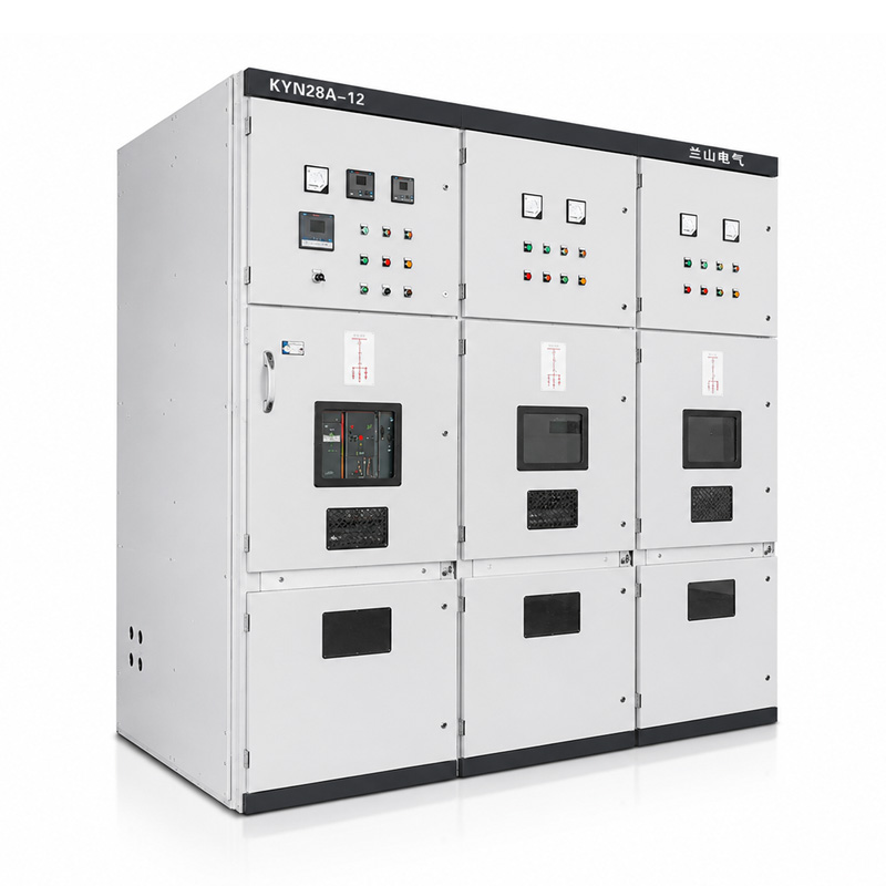
For wider transformer options, review the power transformer range. If the transformer is integrated in a packaged installation, coordinate the transformer review with the enclosure and associated switchgear rather than approving each item in isolation.
Conclusion
Solar transformer overheating at peak generation is a symptom to investigate, not a diagnosis by itself. Align electrical output, reactive power, waveform data, local ambient conditions and cooling status before deciding whether the transformer is overloaded or the thermal margin is being reduced elsewhere.
A strong investigation separates whole-unit heating from local hotspots and uses the exact transformer construction and operating mode. Contact Lanshan Electric with your inverter schedule, temperature records and site conditions to review a solar transformer configuration for the project.
FAQ
Why does a solar transformer get hottest near peak generation?
Peak generation increases current and load-related losses, while the same period may coincide with high local ambient temperature. The final temperature also depends on cooling, reactive-power duty and waveform-related losses, so generation percentage alone is not enough to identify the cause.
Can a solar transformer overheat below its nameplate MVA?
Yes. High ambient temperature, unavailable cooling, harmonic losses or a local electrical hotspot can raise temperatures even when apparent power remains below the nameplate rating. The approved loading conditions and actual measurements need to be reviewed together.
Do solar inverters always require transformer derating?
No universal derating percentage applies to every project. Obtain the inverter harmonic-current spectrum and operating profile, then have the transformer designer evaluate the expected nonsinusoidal-current losses using the applicable engineering method.
Does a high MW reading show the full transformer load?
No. Transformer current relates to apparent power. Reactive power can increase kVA and current even when MW is unchanged. Review MW, MVAr, power factor and current together during the thermal event.
What data should I send for a solar transformer overheating review?
Send time-aligned MW, MVAr or current, transformer temperature, local ambient temperature and cooling-system status. Add inverter details, harmonic measurements where relevant, recent maintenance changes and the exact transformer configuration.