A hot drawer in MNS switchgear is not a diagnosis. The temperature rise may come from sustained current, additional resistance at a plug-in contact, mechanical misalignment, restricted cooling, or simply a measurement taken under different conditions from the comparison circuit.
The useful question is where the heat is being generated and why. This guide gives maintenance teams, plant engineers, and buyers a structured way to investigate drawer-unit overheating without treating withdrawable construction as permission for live work or hot swapping.
Why MNS Switchgear Drawer Units Overheat
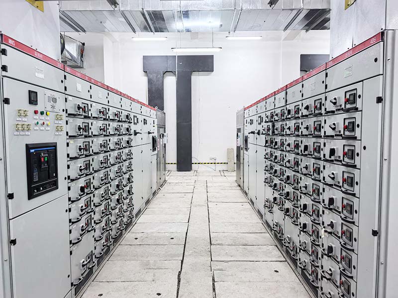
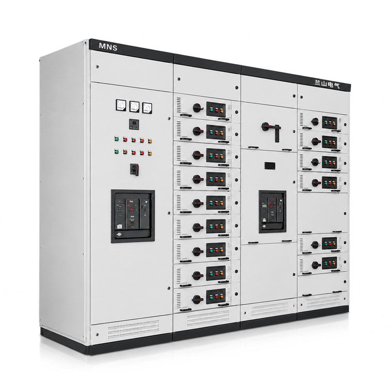
MNS switchgear uses withdrawable functional units so feeder or motor-control circuits can be organized in modular compartments. Lanshan lists an MNS low voltage withdrawable switchgear product for industrial distribution and control applications. The exact drawer arrangement, ratings, separation, and installed devices still need to be confirmed for each project.
Heat can be produced by normal load current, but abnormal temperature usually requires a closer look at the electrical and mechanical path. At a given current, resistive loss follows the relationship P = I²R. A small increase in resistance at a connection can therefore create a concentrated hot spot even when the feeder current has not changed. The basic electrical relationship is explained in OpenStax guidance on electric power.
For MNS switchgear, the investigation should distinguish a local contact problem from a whole-compartment thermal problem. Those two conditions can look similar on a temperature alarm but lead to very different corrective actions.
Make the Equipment Safe Before Any Internal Inspection
Do not rack, withdraw, tighten, clean, or touch a suspected hot drawer while it is energized. Withdrawable equipment is not automatically designed for energized servicing. The applicable operating instructions and site electrical-safety procedures control how a unit is isolated and made safe.
OSHA 1910.333 illustrates the principle that exposed live parts should be de-energized before work unless a recognized exception applies, and that an electrically de-energized condition must be verified. Local regulations and the manufacturer’s instructions govern the actual project.
If MNS switchgear shows smoke, odor, discoloration, repeated protective operation, or rapidly increasing temperature, treat it as an abnormal electrical condition requiring qualified assessment. Do not use a temporary fan, an open door, or a higher trip setting as a substitute for identifying the cause.
Start with the Temperature Pattern, Not the Hottest Color
Thermal imaging can help identify differences between comparable circuits, but the image needs operating context. ISO 18434-1, which remains current after its 2023 review, provides general procedures for thermography used in condition monitoring.
For MNS switchgear, record current, ambient temperature, drawer position, operating time, and the measured surface at the same time as the thermal image. Compare similar phases or similar functional units under similar load whenever possible. A red color on an automatically scaled image is not, by itself, a failure criterion.
| Observed pattern | Possible cause to investigate | Evidence to collect |
|---|---|---|
| One plug-in contact hotter than the other phases | Higher contact resistance, alignment issue, unequal current, or measurement artifact | Phase currents, thermal images under comparable conditions, isolated visual inspection |
| Whole drawer warmer than adjacent units | Higher sustained load, device losses, restricted airflow, or different component mix | Load history, drawer contents, neighboring load, ventilation condition |
| Temperature rises after drawer replacement | Contact engagement, compatibility, alignment, or connection condition | Unit identification, mechanical checks, approved interchangeability records |
| Multiple drawers in one vertical section run hot | Section loading, airflow restriction, ambient temperature, or assembly-level thermal condition | Simultaneous load, room temperature, arrangement drawing, ventilation status |
| Hot spot appears only during motor starting | Starting current and duty cycle rather than steady-state loading | Start frequency, acceleration time, starter data, event-aligned current records |
This evidence matrix prevents the MNS switchgear review from jumping directly to “bad contact” or “overload” before the pattern supports that conclusion.
Check the Actual Load and Its Duration
Begin with the feeder’s measured current and operating history. Compare it with the approved circuit rating and the conditions used to specify the assembly. A drawer serving a motor that runs continuously can have a different thermal duty from an otherwise identical unit carrying an intermittent process load.
For MNS switchgear, do not compare the measured current only with the frame size of the installed breaker or contactor. The circuit rating, conductor size, starter components, connection system, enclosure arrangement, and simultaneous loading all contribute to the assembly’s thermal behavior.
IEC 61439-2:2020 is the current IEC product standard for power switchgear and controlgear assemblies. It includes requirements relevant to temperature-rise verification and withdrawable or removable functional units. The assembly rating must therefore be reviewed as a system, not inferred from one device nameplate.
Do Not Treat a Breaker Setting as the Drawer Rating
Suppose a circuit breaker is adjusted to 200 A. That setting does not prove that every conductor, plug-in contact, starter device, and enclosure arrangement in that MNS switchgear drawer is suitable for continuous operation at 200 A under the actual ambient and grouping conditions. The verified assembly data and project documentation remain the controlling references.
Likewise, a feeder operating below the breaker setting can still experience local heating if the connection resistance has increased. Load and contact condition must be evaluated separately.
Why Contact Resistance Creates Local Hot Spots
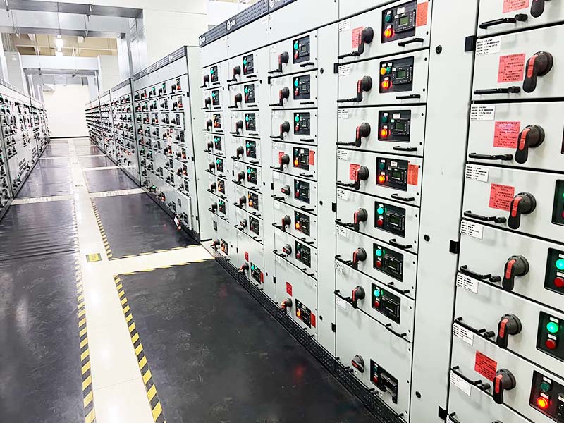
A withdrawable drawer typically relies on defined primary contacts to connect the functional unit to the bus and outgoing circuit. The contact system needs correct engagement, adequate contact pressure, suitable surface condition, and compatibility with the verified design.
In MNS switchgear, contamination, wear, mechanical damage, inadequate engagement, or another source of increased resistance can concentrate heating at a small interface. The I²R relationship explains why the same current can produce more heat after resistance increases.
Do not infer the defect from temperature alone. During an approved isolated inspection, qualified personnel should compare the contact surfaces, mechanical condition, and engagement with the manufacturer’s criteria. Any resistance measurement or contact-force assessment should follow the appropriate equipment procedure.
A Simple Illustrative Comparison
Assume two otherwise identical connections each carry 160 A. If one connection has an effective resistance of 80 micro-ohms and another has 200 micro-ohms, the simplified resistive losses are approximately 2.05 W and 5.12 W respectively. The second connection produces about 2.5 times the localized loss at the same current.
These values are hypothetical and are not acceptance limits for Lanshan equipment. Real contact systems have complex heat paths, and field resistance measurements require appropriate instruments and interpretation. The example only shows why a modest resistance change can matter in MNS switchgear.
Check Drawer Alignment and Mechanical Engagement
Withdrawable construction adds mechanical interfaces that fixed equipment does not have. The drawer must reach the intended service position and its primary and auxiliary connections must engage as designed. A unit that appears closed from the front can still require a mechanical review if temperature or operating history indicates an abnormal condition.
For MNS switchgear, investigate whether the drawer was recently removed, replaced, or exchanged with another unit. Confirm the unit identity, size, rating, mechanical coding, and manufacturer-approved interchangeability. Similar external dimensions do not prove that two drawers are electrically and mechanically interchangeable.
Look for evidence of uneven contact marks, distortion, loose support parts, or operating difficulty only after the equipment has been made safe. If the mechanism does not move normally, do not use additional force to obtain engagement. The cause should be resolved against the approved drawings and instructions.
Separate Main Contacts from Contactor and Starter Heating
Not every hot point inside a motor-control drawer is a bus connection. A contactor, overload relay, fuse, circuit breaker, semiconductor device, or control transformer can be the dominant heat source depending on the circuit.
IEC 60947-4-1:2023 applies to electromechanical contactors and motor-starters within its scope. When an MNS switchgear drawer contains these devices, review their selected ratings and operating duty as well as the assembly-level requirements.
A contactor that operates frequently can have a different thermal and mechanical history from one that remains closed for long periods. Motor starting frequency, acceleration time, utilization category, and ambient conditions should be part of the investigation if the hotspot is associated with the starter rather than the plug-in contacts.
Review Section Loading and Cooling Conditions
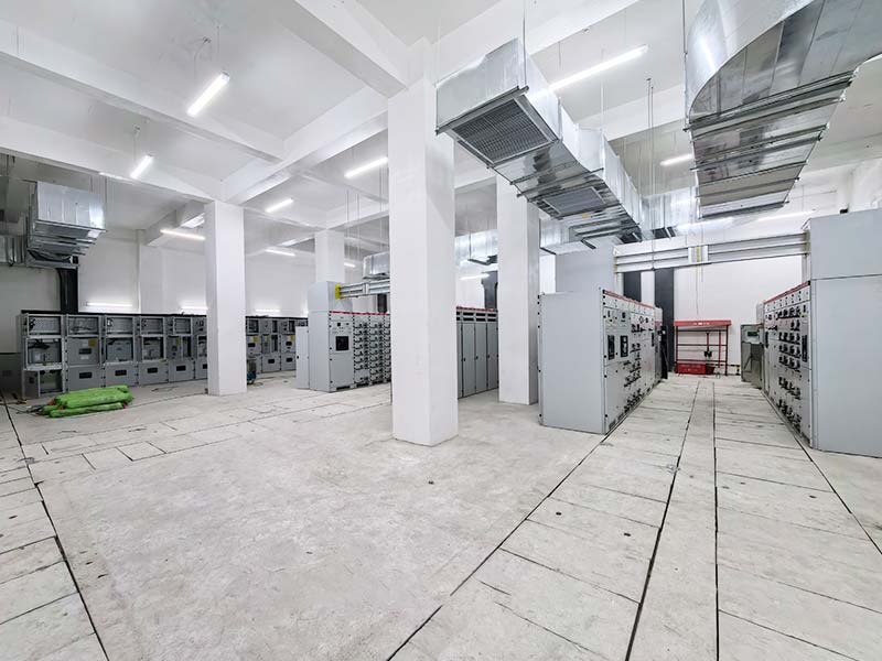
A single MNS switchgear vertical section may contain several functional units. Even when every drawer is within its individual circuit rating, the combined losses can raise the local air temperature if the actual simultaneous loading differs from the condition used for the design verification.
Check whether adjacent high-load drawers were added, spare units were commissioned, filters were installed, ventilation openings were obstructed, or room temperature increased after process changes. These changes can alter the thermal environment without changing the affected feeder itself.
Do not leave panel doors open to cool MNS switchgear. The enclosure configuration is part of the equipment’s protection and thermal design. Any change to ventilation, filters, fans, or internal barriers should receive manufacturer or engineering review against the required assembly characteristics.
Look Beyond the Switchboard Room Thermostat
Measure the air condition relevant to the equipment, not just the building-management sensor on another wall. A switchroom can have localized recirculation or hot-air pockets around a heavily loaded lineup. Correlate cabinet temperature with the same time period as the electrical load.
If forced ventilation is provided, confirm actual operation rather than only the control command. A running fan with a blocked inlet or restricted filter may not deliver the expected cooling.
Use Phase Imbalance as Evidence, Not an Automatic Diagnosis
Compare phase currents where the circuit permits meaningful comparison. One phase carrying more current will naturally generate greater conductor and contact losses, so a hotter phase does not automatically prove a defective connection.
For MNS switchgear, ask whether the load itself is unbalanced, whether harmonics are significant, and whether the temperature difference remains disproportionate after current differences are considered. This is particularly important for mixed single-phase loads and electronically controlled equipment.
If the current is nearly equal but one comparable contact is much hotter, resistance or mechanical condition becomes a stronger hypothesis. If both current and temperature are higher on the same phase, the review must separate load contribution from connection condition.
Distinguish Temperature-Rise Verification from Field Trending
IEC assembly verification and field condition monitoring answer different questions. Verification establishes that a defined design meets its requirements under specified conditions. Field trending asks whether an installed unit is changing or behaving differently from comparable equipment.
A thermal image from MNS switchgear should not be presented as a substitute for design verification. Likewise, a design-verification report does not prove that a ten-year-old field contact remains in its original condition.
Use both forms of evidence appropriately: verified design data to define the equipment capability, and operating history to identify developing problems. When configuration changes are made, confirm whether the previous verification basis still applies.
Example: One Drawer Runs Hot After a Production Expansion
Consider a hypothetical factory where an MNS switchgear drawer supplies a process motor. The drawer has operated for several years without unusual temperature indications. After a production expansion, the motor runs for longer periods and nearby spare drawers are also placed into service.
A thermal survey now shows the affected drawer is warmer than before. The first step is not to replace the drawer. The review aligns current, ambient temperature, neighboring section loading, and thermal images with the same operating period.
Suppose the feeder current increased by 12%, the neighboring section became more heavily loaded, and all three phases of the drawer warmed by a similar amount. That pattern supports an investigation of sustained duty and section thermal conditions before assuming a single damaged contact.
If, instead, one phase contact is much hotter while the three phase currents remain similar, a localized connection or alignment issue becomes a higher-priority hypothesis. The MNS switchgear should then be isolated and inspected by qualified personnel according to the approved procedures.
The important point is that the same symptom—“drawer overheating”—can arise from different mechanisms. Evidence should determine the corrective action.
What to Record Before Asking for a Replacement Drawer
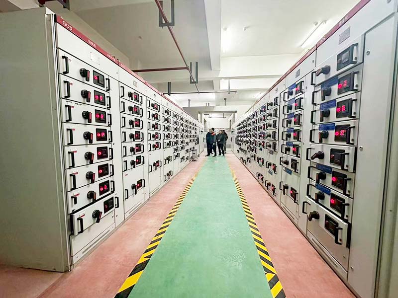
When a replacement or retrofit is being considered, send the manufacturer more than a photograph of the hot area. For MNS switchgear, provide the assembly identification, drawer designation, circuit function, load history, installed devices, thermal evidence, and details of any recent change.
| Information to provide | Why it matters |
|---|---|
| Assembly nameplate and drawing reference | Identifies the verified equipment family and arrangement |
| Drawer number and circuit function | Connects the observation to the feeder or motor duty |
| Measured current by phase and operating duration | Separates loading from purely local heating |
| Thermal images with ambient and timestamp | Allows comparison under known conditions |
| Installed breaker, contactor, overload and control devices | Checks the actual functional-unit configuration |
| Recent replacement, racking, maintenance or expansion history | Highlights mechanical or system changes |
| Required spare or interchangeability objective | Defines whether an identical replacement or engineering retrofit is needed |
Lanshan’s MNS low voltage withdrawable switchgear can be reviewed against a project’s feeder and motor-control requirements. Request confirmation of the exact drawer arrangement, ratings, internal separation, and applicable verification for the proposed configuration.
Prevent Repeat Heating in New MNS Switchgear Projects
For a new project, prevention starts with accurate feeder duties and a layout that reflects simultaneous operation. Provide the motor or feeder schedule, design currents, starting methods, operating cycles, room conditions, and required maintenance philosophy before the assembly is finalized.
Agree how spare drawers will be identified and controlled. A spare is valuable only when its electrical devices, coding, connections, and mechanical arrangement are compatible with the circuit for which it is intended. Do not define interchangeability solely by drawer size.
Specify which operating data should be recorded after commissioning. Baseline thermal images under known load can make future MNS switchgear comparisons more meaningful, provided the site has an approved thermography program and qualified personnel.
Finally, keep final drawings, settings, device schedules, and routine-verification records with the equipment. Maintenance decisions are more reliable when the field team can compare the installed configuration with what was actually approved.
Conclusion
MNS switchgear overheating should be investigated as an evidence problem, not solved by guessing at the hottest component. Compare current, duration, contact condition, drawer alignment, section loading, and the measurement method before selecting a corrective action.
If a drawer or functional unit needs replacement or redesign, contact Lanshan Electric with your feeder schedule, assembly information, and thermal records. A configuration review can then focus on the actual duty and interfaces rather than an isolated temperature reading.
FAQ
Why does an MNS switchgear drawer get hot?
Possible contributors include sustained load, increased contact resistance, mechanical misalignment, starter-device losses, poor cooling, and phase imbalance. Use time-aligned current and temperature evidence to distinguish them before concluding that one component has failed.
Can an MNS switchgear drawer be withdrawn while energized?
Do not assume so. Withdrawable construction is not a general permission for energized servicing or hot swapping. Follow the manufacturer’s operating instructions, the approved equipment positions, and the applicable electrical-safety procedures.
Does a hotter phase always mean a bad contact?
No. Higher current on one phase can create higher normal losses. Compare phase currents, thermal conditions, and similar connection points. A disproportionate temperature difference at similar current is stronger evidence of a localized issue.
Can thermal imaging confirm the exact cause of switchgear overheating?
Thermography can reveal temperature patterns, but it does not by itself identify the root cause. Load, emissivity, reflections, ambient conditions, and equipment configuration all affect interpretation. Use it as one part of a structured investigation.
What should I send when requesting a replacement MNS drawer?
Send the assembly identification, drawer designation, circuit duty, phase currents, installed devices, drawings, thermal records, and any maintenance or expansion history. Ask the manufacturer to confirm mechanical and electrical compatibility rather than relying on drawer dimensions alone.